2D photoelectric auto collimation equipment and measuring method based on dynamic differential compensation process

A differential compensation and dynamic technology, applied in the direction of optical devices, measuring devices, instruments, etc., can solve the problem of poor measurement stability and repeatability of photoelectric autocollimators, difficulty in further improving measurement uncertainty, and limitations of photoelectric autocollimation In order to simplify the measurement process and data processing, improve measurement stability and repeatability, and meet the needs of high-precision two-dimensional small-angle measurement

Active Publication Date: 2005-10-26
日照大象房屋建设有限公司
View PDF4 Cites 57 Cited by
  • Summary
  • Abstract
  • Description
  • Claims
  • Application Information

AI Technical Summary

Problems solved by technology

[0012] However, in practical applications, especially from the optical path, mechanical structure and measurement process, it can be seen that the above measurement schemes have the following shortcomings: since no error compensation or correction is used, the angular drift of the beam is not eliminated during the measurement process , and finally mix the angle measuremen

Method used


Image

  • 2D photoelectric auto collimation equipment and measuring method based on dynamic differential compensation process
  • 2D photoelectric auto collimation equipment and measuring method based on dynamic differential compensation process
  • 2D photoelectric auto collimation equipment and measuring method based on dynamic differential compensation process

Examples


Embodiment 1

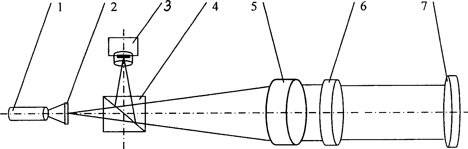
[0070] Such as figure 1 As shown, the spectroscopic lens 6 is firstly adjusted so that the reference spot 13 received on the CCD image sensor 3 is completely separated from the measurement spot 12, so as to avoid the light spot received on the CCD image sensor 3 due to overlapping of the measuring beam 11 and the reference beam 10. For the problem that the center cannot be positioned accurately, the spectroscopic lens 6 should be fixed after the adjustment, and then the device should be calibrated. After calibration, the spectroscopic lens 6 should not be adjusted during use of the device. When measuring, light source 1 adopts laser 17, and the light beam that sends illuminates the etched part 19 light-transmitting reticle 20 that is positioned at the focal point of collimating objective lens 5, and after passing through dichroic prism 4, the transmitted light beam passes through collimating objective lens 5 and becomes The parallel collimated light beam is incident on the bea...

Embodiment 2

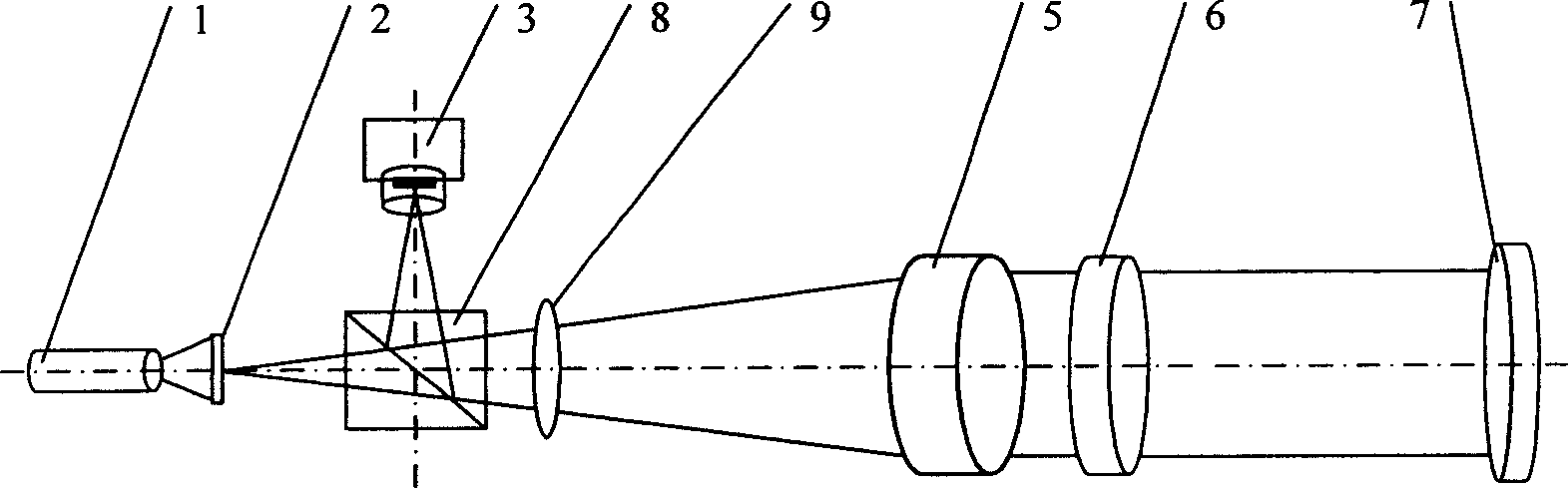
[0075] Such as figure 2 As shown, using polarized light to achieve the purpose of reducing light energy loss, firstly adjust the spectroscopic lens 6 so that the reference spot 13 received on the CCD image sensor 3 and the measurement spot 12 are completely separated, avoiding the measurement beam 11 and the reference beam 10 due to The overlap of light beams leads to the problem that the light spots received on the CCD image sensor 3 cannot be accurately positioned. After the adjustment, the spectroscopic lens 6 should be fixed, and then the device should be calibrated. After calibration, the spectroscopic lens 6 should not be adjusted during use of the device. During measurement, light source 1 adopts laser 17, and the light beam that sends illuminates the etched portion 19 light-transmitting reticle 20 that is positioned at the focal point of collimating objective lens 5, and the light beam becomes polarized light after passing through polarization beam splitter prism 8, an...

Embodiment 3

[0080] Such as figure 1 As shown, light source 1 adopts light-emitting diode (LED) 18, and the light beam that sends illuminates the etched portion 19 light-transmitting reticle 20 that is positioned at the focal point of collimating objective lens 5, and other parts and working principle of the present embodiment are all the same as Example 1 is the same.


PUM

PropertyMeasurementUnit
Surface roughnessaaaaaaaaaa

Abstract

The invention belongs to the precise instrument manufacturing and detecting technology, especially relates to the bidimensional photoelectric self-alignment equipment and method based on dynamic differentiation compensation method. The equipment comprises the light source, the calibrated board, the CCD image sensor, the beam splitter prism, the aligning object lens, the measuring reflecting lens and the beam splitter between the aligning object lens and the reflecting lens. The two faces of the beam splitter are separately plated with the splitting film and the reflection reducing coating; the surface coarseness of the photic base plate is more than 0.08 um, and paralleling degree of the two faces is smaller than 10'; the light splitting ratio is 52/48 is less than or equal to T/R is less than or equal to 72/28 and the reflection reducing coefficient alpha is greater than or equal to 99%. The invention improves the stability and the repetition of the measuring.

Description

technical field [0001] The invention belongs to the technical field of precision instrument manufacturing and precision testing and measurement, and in particular relates to a high-precision two-dimensional photoelectric self-collimation device and a measurement method for real-time compensation of the angular drift of light beams based on a dynamic differential compensation method. Background technique [0002] With the continuous improvement and improvement of measurement technology, the development of modern high-precision measurement technology and azimuth targeting and tracking system has put forward higher and higher requirements for the measurement accuracy of small angles. Photoelectric autocollimator plays an irreplaceable role in small-angle precision measurement, high-precision aiming and positioning. It can be used as a component of optical measuring instruments such as goniometers and optical comparators, and can also be used alone in measuring instruments for op...

Claims


Application Information

Patent Timeline
IPC IPC(8): G01B11/26
Inventor 谭久彬敖磊崔继文黄向东
Owner 日照大象房屋建设有限公司
Why Eureka
Try Eureka