High efficient LED

A technology of light-emitting diodes and light-emitting diodes, applied in optics, electric light sources, optical components, etc., can solve the problems of large size, heavy weight, and low light extraction efficiency of conical condensing lenses, so as to improve the effective luminous efficiency, high Color rendering index, high luminous efficiency

Inactive Publication Date: 2005-10-26
葛世潮
View PDF0 Cites 11 Cited by
  • Summary
  • Abstract
  • Description
  • Claims
  • Application Information

AI Technical Summary

Problems solved by technology

Since the size of the reflective bowl is much larger than that of the chip, the light emitted by the chip is reflected by the reflective bowl to form a virtual image with a size much larger than that of the chip, which makes the light concentrating effect worse. Increased multiple reflections at the interface of optical media, lenses and air, increased light loss, and low light utilization; especially for high-power light-emitting diodes, because of their large chip size and poor light-gathering effect
In order to obtain a good light-concentrating effect, the high-power light-emitting diodes of the prior art usually require a large conical light-concentrating lens in addition to a large-sized reflective bowl. The light-emitting diodes with this structure not only have low light utilization , and its conical condenser lens is large in size, heavy in weight, high in cost, and inconvenient to install
[0003] Secondly, the light emitting angles of the existing light-emitting diode chips are all less than 2π, the loss of light emitted by the chip is large, and the light extraction efficiency is low, that is, the effective luminous efficiency of the light-emitting diode is low

Method used


Image

  • High efficient LED
  • High efficient LED
  • High efficient LED

Examples


Embodiment Construction

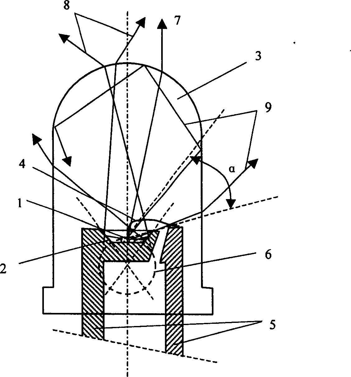
[0022] The markings in the accompanying drawings are as follows:

[0023] 1-chip 2-reflector bowl 3-lens

[0024] 4-Electrical connection line 5-Leader line 6-Virtual image

[0025] 7-Output Ray 8-Output Ray 9-Output Ray

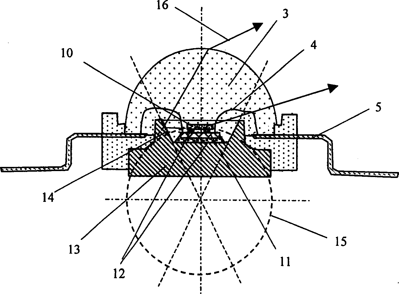
[0026] 10-chip 11-silicon substrate 12-solder or thermal paste

[0027] 13-Metal Base 14-Light Reflecting Bowl 15-Virtual Image

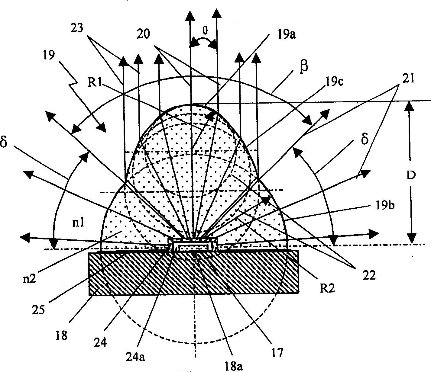
[0028] 16-output light 17-chip 18-metal base

[0029] 18a-Metal base plane 18b-Metal base mesa 18c-Metal base cone

[0030] 18d-Metal base multi-mesa 18e-Metal base cone 19-Lens

[0031] 19a - Lens top 19b - Bottom lens 19c - Lens middle part

[0032] 19d-Lens fixing foot 20-Output light 21-Output light

[0033] 22- Lens transition surface 23- Output light 23- Output light after reflection

[0034] 24-luminescent powder layer 24a-translucent medium layer 25-medium layer

[0035] 26-Output light 27-Insulation layer 28-Conductive layer

[0036] 29-Screw 30-Medium Layer 31-Light Emitting Diode

[0037] 32-light reflector 3...


PUM


Abstract

A high efficient light emitting diode includes at least one diode chip, a high thermal conductivity metal base without any reflecting bowls, among which, the chip is installed in said metal base positively or up side down, a lens with a special curved face is set above the chip composed of three parts: the top is a sphere with radius R1, the distance D from its top to the chip is K R1 n2 / (n1-n2), in which, n2 n1 are the lens medium and air index of refraction separately K is a constant, the value is decided by the needed light output angle, the second part is a sphere with the radius R2 near the chip place, its core is on the chip or close to it, the third part is a sphere between the two spheres, the curvature radius is between R1 and R2.

Description

technical field [0001] The invention relates to a high-efficiency light-emitting diode, which can be used to manufacture high-efficiency light-emitting diodes, concentrated light-emitting diodes and lighting lamps with different light output angles, and is used for lighting, automobile lights, miner's lamps, spotlights, stage lights, aircraft and Reading lamps, traffic lights, and displays for automobiles, etc. Background technique [0002] The light-emitting diode in the prior art usually installs the light-emitting diode chip in a reflective bowl. There is a light-transmitting medium and a lens in front of the chip. The light emitted by the light-emitting diode chip is reflected by the reflective bowl and concentrated by the lens before exiting. Since the size of the reflective bowl is much larger than that of the chip, the light emitted by the chip is reflected by the reflective bowl to form a virtual image with a size much larger than that of the chip, which makes the li...

Claims


Application Information

Patent Timeline
IPC IPC(8): H01L33/58H01L33/60
CPCH01L2924/181H01L2224/48091H01L2224/48137H01L2224/48247H01L2224/73265H01L2924/00014H01L2924/00012
Inventor 葛世潮
Owner 葛世潮
Why Eureka
Try Eureka