
Zero voltage, zero current switch type inverter based on transformer auxiliary current converting

A transformer and zero-current technology, applied in the field of zero-voltage, zero-current switching inverters, can solve the problems of lowering the switching frequency of the inverter, lowering the reliability of the inverter system, increasing the switching loss of the inverter, etc. Reduced losses and improved power conversion efficiency

Inactive Publication Date: 2005-10-26
SHANGHAI JIAO TONG UNIV
View PDF0 Cites 7 Cited by
  • Summary
  • Abstract
  • Description
  • Claims
  • Application Information

AI Technical Summary

Problems solved by technology

[0003] After searching the existing technical documents, it was found that the document "Analysis, Design and Experiment of Zero-Voltage Inverter Based on Transformer-Assisted Commutation" published by Xiaoming Yuan and Ivo Barbi (Acta Power Electronics, (USA) Electrical and Electronic Engineers Association, 15(1), 2000, pp.72-82) mentioned that there are two fatal flaws in the auxiliary resonant converter inverter topology: (1) when the load current is positive and negative half cycle output When the current is seriously asymmetrical or the inverter output is seriously overloaded, and the high-frequency resonant inductance element is saturated or biased, the conduction current of the auxiliary switch will increase several times. If the auxiliary power tube is easily turned on or off at this time, The auxiliary power tube will face the danger of overvoltage and overcurrent, and eventually lead to damage, and the reliability of the inverter system will be greatly reduced; (2) All types of auxiliary resonant converter inverters currently have auxiliary commutation time The duration is proportional to the magnitude of the load current. When the load current is large, the auxiliary commutation time of the inverter is also large, which will lead to a significant reduction in the switching frequency of the inverter. At the same time, if the inverter cannot be adjusted in time The auxiliary commutation time will not ensure that the main power tube of the inverter is commutated under the conditions of zero voltage and zero current, which will lead to a sharp increase in the switching loss of the inverter, and even cause damage to the power switch tube
Therefore, in the topology of the auxiliary resonant converter inverter, it is often necessary to use some special control means to control the turn-off time of the auxiliary switch tube, that is, to turn off the auxiliary switch tube when the resonant current decays to zero. The main purpose is to prevent The danger of overvoltage breakdown of the auxiliary switch tube, but this solution greatly increases the complexity of the control circuit, and also seriously affects the switching frequency, output duty cycle and other indicators of the inverter
The above two defects will cause the ARCP inverter to fail to operate stably under some relatively harsh working conditions, and even cause the ARCP inverter to fail and stop running.

Method used


Image

  • Zero voltage, zero current switch type inverter based on transformer auxiliary current converting
  • Zero voltage, zero current switch type inverter based on transformer auxiliary current converting
  • Zero voltage, zero current switch type inverter based on transformer auxiliary current converting

Examples


Embodiment Construction

[0020] Provide following embodiment in conjunction with content of the present invention:

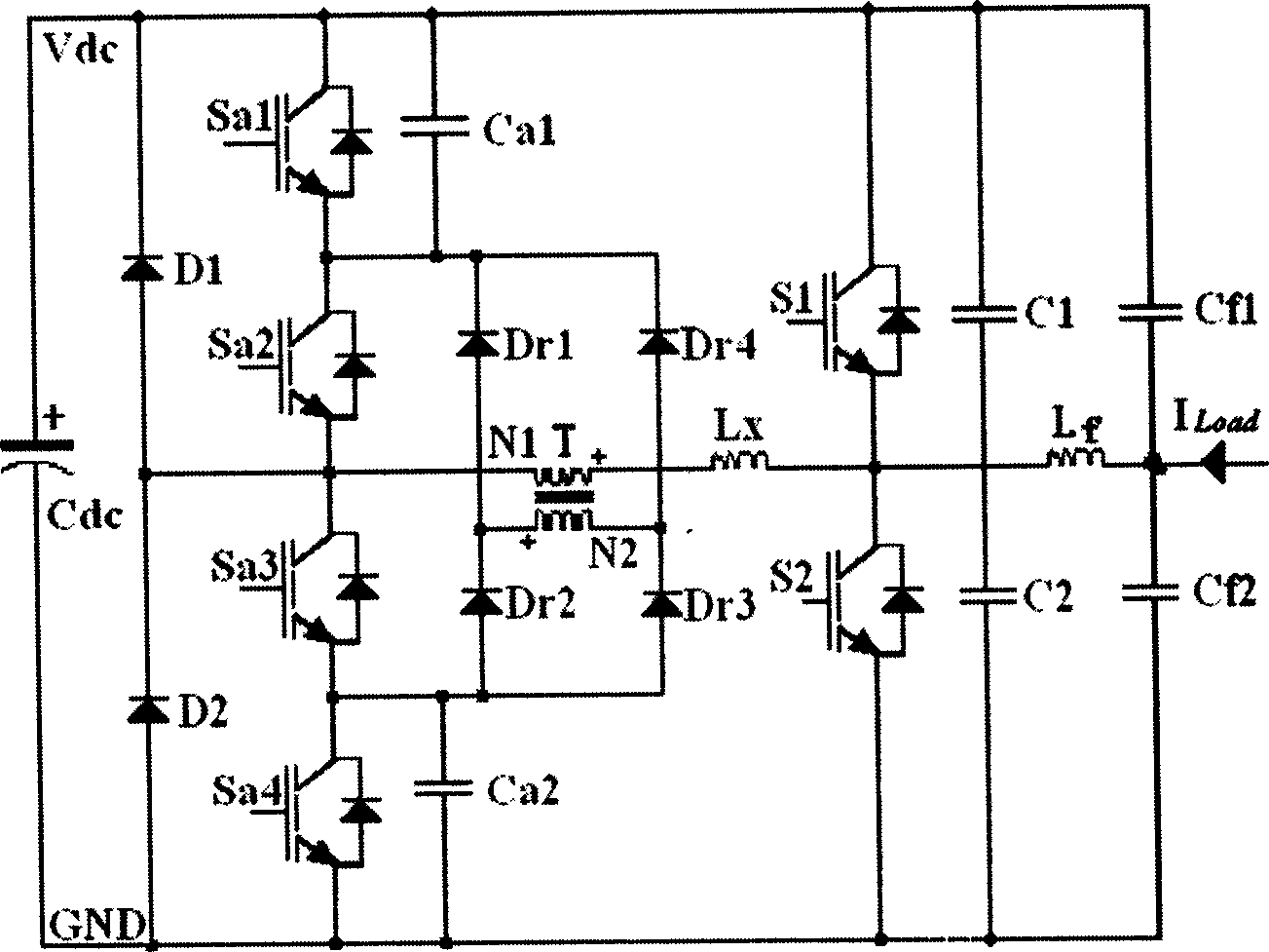
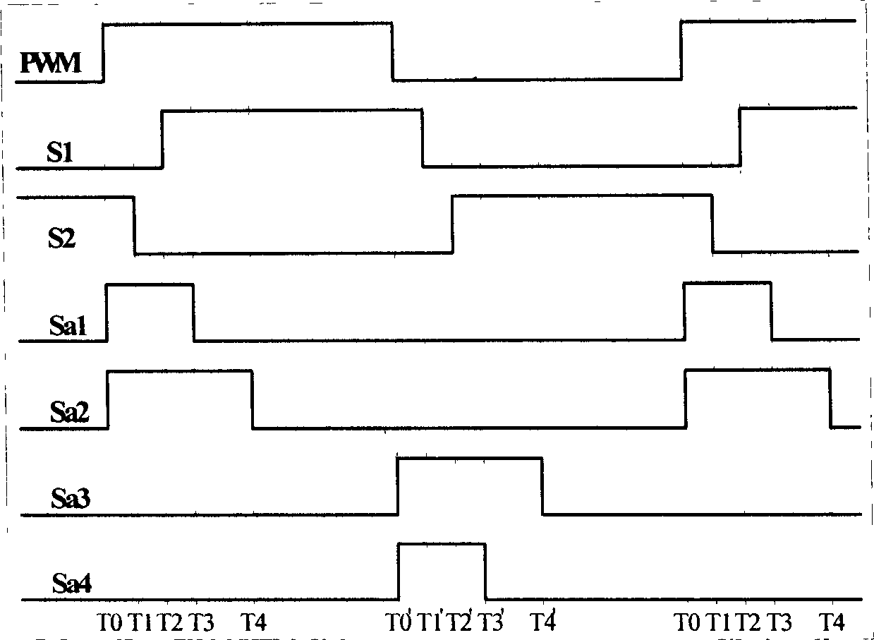
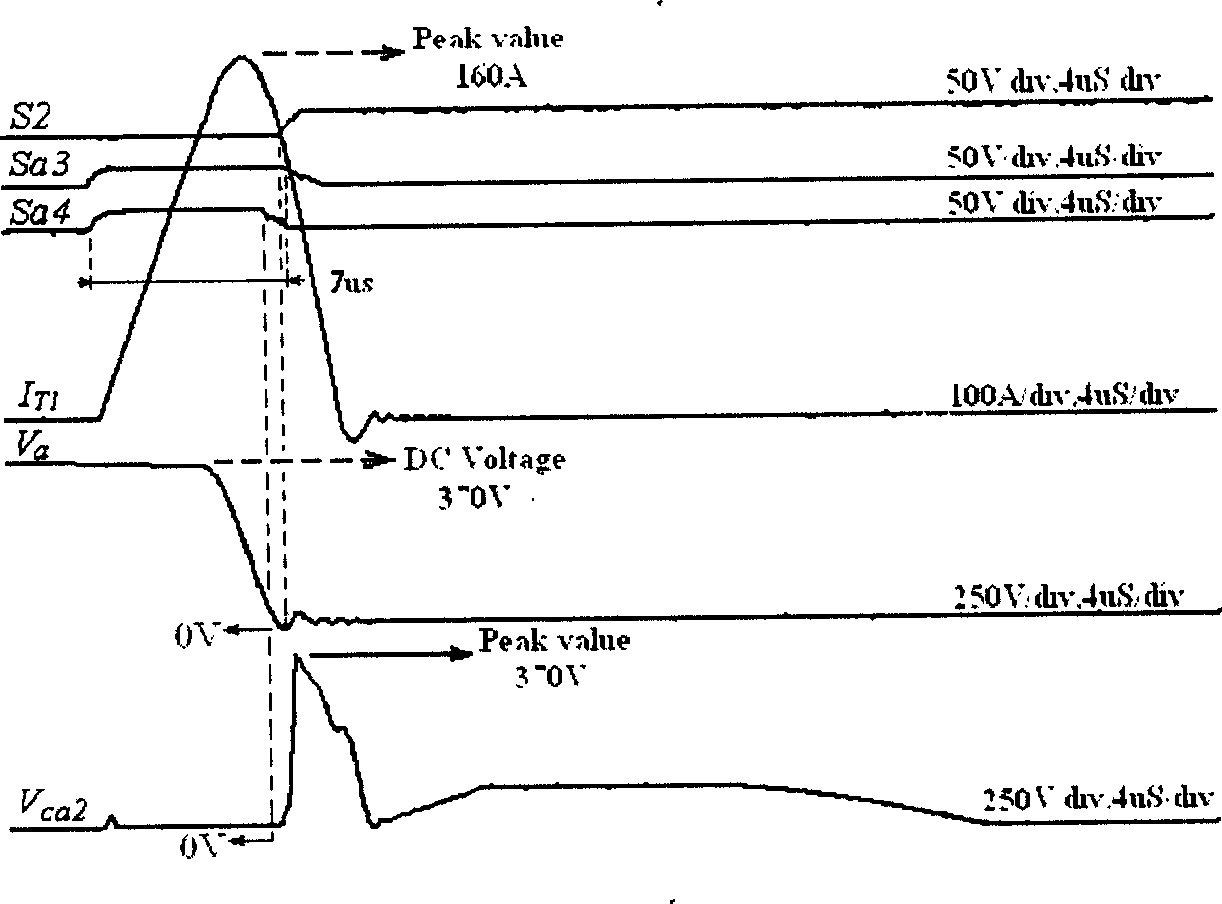
[0021] Such as figure 1 , 2 As shown, when the load current is borne by the anti-parallel diode of the upper half-bridge power switch S1 (off state), the system requires the lower half-bridge power switch S2 to be turned on for commutation (operation from off to on ), the inverter controller first sends the auxiliary resonant power switch Sa3, Sa4 signal, when they are turned on, the resonant current i in the resonant circuit T1 rises linearly and gradually rises to I Load, at this time the auxiliary resonant capacitor C2 (parallel capacitor of the main power switch S2) starts to discharge through the auxiliary resonant circuit, and its voltage gradually decays to zero. When its voltage reaches zero, the inverter system has created a zero-voltage conduction condition for the conduction of the main power switch. At this time, the inverter controller sends a conduction signal of the ma...


PUM


Abstract

A zero-voltage, zero current assistant resonance conversion inverter based on a transformer assistant inversion includes a master inverse part, an assistant resonance conversion part, an output low pass filter, among which, the master inverse part is parallel to the assistant resonance conversion part, each of them has a public connection point at its own central point, the output filter is connected at the output of the master inverse part and serial with the load. This invention acknowledges that the master switch is turned on or off at zero voltage and the assistant switch is turned on or off at zero voltage or zero current to greatly increaser the conversion efficiency, stability of electric energy.

Description

technical field [0001] The invention relates to an inverter in the technical field of power electronic commutation and inversion, in particular, a zero-voltage, zero-current switching inverter based on transformer auxiliary commutation. Background technique [0002] At present, most of the topologies of auxiliary resonant converter inverters can create zero voltage and zero current conditions for inverter commutation, so as to achieve the purpose of soft switching. [0003] After searching the existing technical documents, it was found that the document "Analysis, Design and Experiment of Zero-Voltage Inverter Based on Transformer-Assisted Commutation" published by Xiaoming Yuan and Ivo Barbi (Acta Power Electronics, (USA) Electrical and Electronic Engineers Association, 15(1), 2000, pp.72-82) mentioned that there are two fatal flaws in the auxiliary resonant converter inverter topology: (1) when the load current is positive and negative half cycle output When the current i...

Claims


Application Information

Patent Timeline
IPC IPC(8): H02M7/48
CPCY02B70/1491Y02B70/10
Inventor 曼苏乐姚钢陈陈
Owner SHANGHAI JIAO TONG UNIV
Learn More