Synchronous rectification switching power supply

A technology of synchronous rectification switch and power supply device, which is applied in the direction of high-efficiency power electronic conversion, conversion equipment with intermediate conversion to AC, and climate sustainability. The problems such as excitation oscillation and large loss can be avoided, and the effects of preventing through current, increasing switching frequency, and reducing miniaturization can be achieved.

Inactive Publication Date: 2005-11-02
COSEL
View PDF1 Cites 8 Cited by
  • Summary
  • Abstract
  • Description
  • Claims
  • Application Information

AI Technical Summary

Problems solved by technology

In this case, there is a problem that the main switching element is turned on when the rectifying element is not turned off, and a very large inrush current flows through the main switching element, and the circuit on the secondary side of the power supply unit becomes short-circuited. The through current flows through the stage end circuit, causing damage to the main switching element or synchronous rectification element, etc.
The loss during the rectification period of this diode is larger than that during the conduction period of the rectification element of the MOS-FET
Therefore, there is a problem that although it is desirable to shorten the dead time as much as possible, the dead time td cannot be shortened in order to reliably turn off the synchronous rectifier element before the main switching element is turned on.
Furthermore, since the dead time td cannot be shortened, the switching frequency cannot be increased, which hinders the miniaturization and cost reduction of the device.
[0008] In addition, when a voltage equal to or higher than the set voltage is applied from the outside between the output voltage terminals, or when the power supply is stopped when an external large-capacity capacitor is added between the output terminals, there is a problem that the secondary The synchronous rectification element on the secondary side is turned off and a through current flows, or the circuit on the secondary side self-oscillates due to the power of a large-capacity external capacitor connected between the output terminals

Method used


Image

  • Synchronous rectification switching power supply
  • Synchronous rectification switching power supply
  • Synchronous rectification switching power supply

Examples


Embodiment Construction

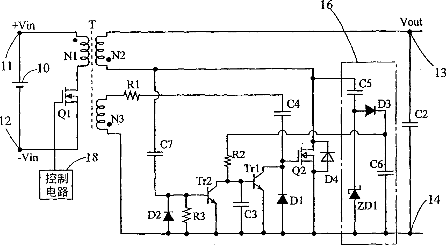
[0026] Embodiments of the present invention will be described below with reference to the drawings. figure 2 A circuit of the flyback type synchronous rectification switching power supply device according to the first embodiment of the present invention is shown. In this switching power supply circuit, a DC power supply 10 is connected between input terminals 11 and 12, and a primary winding N1 of a transformer T and a main switching element Q1 of a MOS-FET are connected in series. On the input terminal 11 of the positive end of the DC power supply 10, a terminal generating a positive voltage when the main switching element Q1 is turned on is connected to the terminal on the dotted side of the primary coil N1, and the terminal on the non-dot side of the transformer T. is connected to the drain of the main switching element Q1. In addition, the source of the main switching element Q1 is connected to the input terminal 12 of the negative terminal of the DC power supply 10, and...


PUM


Abstract

There is provided a flay-back type synchronous rectifying switching power supply device in which a rectifying element is surely turned off before the main switch is turned on even when the on-time of a main switch element is lengthened due to sudden variation of a load. The synchronous rectifying switching power supply device is equipped with a synchronous rectifying element (Q 2 ) connected to a secondary winding (N 2 ) of a transformer (T) in series and driving means comprising an auxiliary winding (N 3 ), etc. for turning on the synchronous rectifying element (Q 2 ) complementarily with a main switch element (Q 1 ) between output terminals ( 13, 14 ). A transistor (Tr 1 ) serving as interrupting means for turning off the synchronous rectifying element (Q 2 ) is provided between the gate and source of the synchronous rectifying element (Q 2 ). An off-timing at which the synchronous rectifying element (Q 2 ) is turned off by the interrupting means (Tr 1 ) is set within a timing range which corresponds to a fixed time after the main switch element (Q 1 ) is turned on and also is as near as a fixed driving period of the main switch element (Q 1 ).

Description

technical field [0001] The present invention relates to a synchronous rectification switching power supply (switching power supply) which converts DC voltage into a desired voltage and supplies it to electronic equipment, and particularly relates to a flyback type (flyback) synchronous rectification switching power supply device. Background technique [0002] In the existing switching power supply device-flyback converter equipped with a synchronous rectification rectification circuit, for example, as disclosed in (Japanese) Unexamined Patent Publication No. 2000-116122, a DC power supply and a main switching element are connected to the primary coil end of the transformer. A series circuit composed of a synchronous rectification element is arranged in series on the secondary coil of the transformer, and then connected to the output terminal through the rectification circuit. The flyback converter performs switching control on the main switching element of the MOS-FET. When ...

Claims


Application Information

Patent Timeline
Patent Type & Authority Applications(China)
IPC IPC(8): H02M3/28
CPCY02B70/1475
Inventor 高岛诚广川芳通
Owner COSEL
Why Eureka
Try Eureka