Fluid driven, single-freedom and flexible bending joint

A bending joint, fluid-driven technology, applied in artificial arms, artificial legs, manipulators, etc., can solve problems such as the inability to obtain a more accurate mathematical model for the bending deformation of the rubber wall, the poor dynamic control effect, and the insensitive movement, etc., to achieve dynamic control. High precision, small duty cycle, and low power/mass ratio

Inactive Publication Date: 2005-11-09
JIANGNAN UNIV
View PDF0 Cites 14 Cited by
  • Summary
  • Abstract
  • Description
  • Claims
  • Application Information

AI Technical Summary

Problems solved by technology

[0002] Before the present invention was made, in the prior art, for bending joints: generally, various types of motors or hydraulic pressure were used as power, and various mechanical structures, or hydraulic cylinders and motors, or their combinations were used as actuators; Each method is a rigid structure, complex structure, large volume, high manufacturing cost
There is also a curved joint that adopts a rubber wall (a circular rubber tube that can deform axially) through compressed air. Since the rubber wall will expand in both the axial and radial directions, the radial expansion is a waste of energy and is harmful to the user. The bending deformation of the rubber wall cannot obtain a more accurate mathematical model, so the dynamic control effect is not good, and the action is not sensitive enough

Method used


Image

  • Fluid driven, single-freedom and flexible bending joint
  • Fluid driven, single-freedom and flexible bending joint
  • Fluid driven, single-freedom and flexible bending joint

Examples


Embodiment Construction

[0020] Below the present invention will be further described in conjunction with the embodiment in the accompanying drawing:

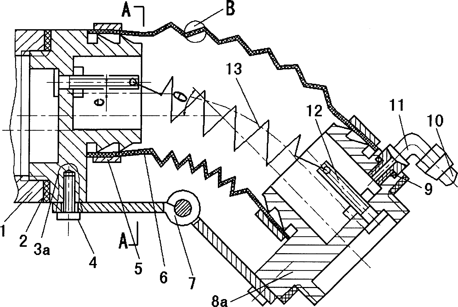
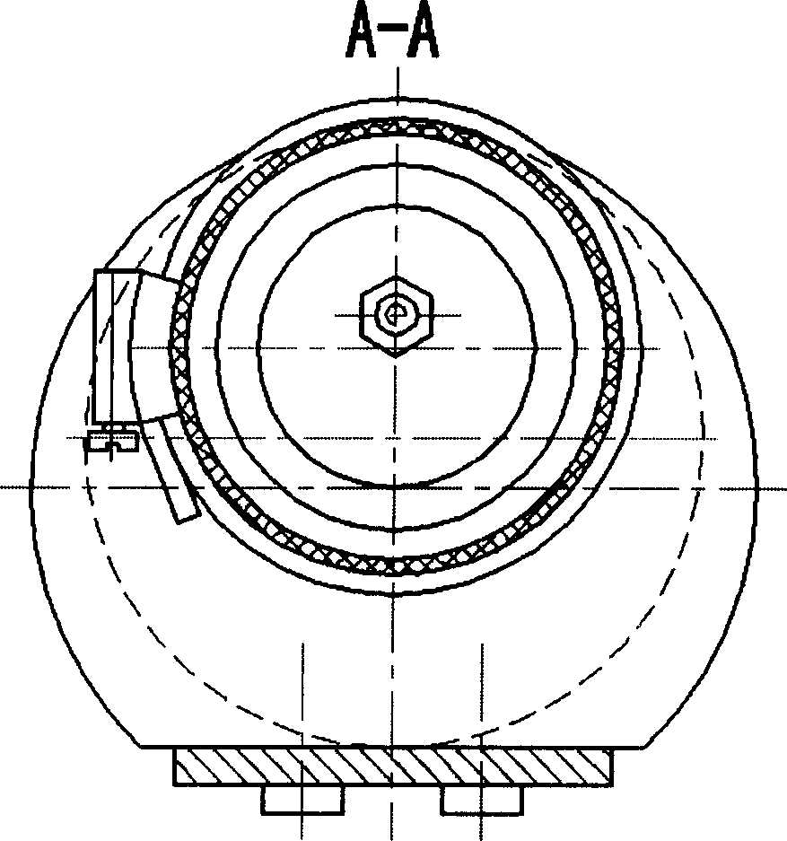
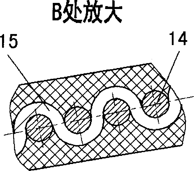
[0021] The present invention mainly consists of a finger cot 1, an adjusting gasket 2, a head seat 3a, a non-porous head seat 3b, a screw 4, a hoop 5, an elastic wave shell 6, a plate hinge 7, a tail stock 8a, a non-porous tail stock 8b, a seal Ring 9, hose 10, joint 11, hook shaft 12, tension spring 13, annular weft 14, warp 15, elastic strip 16, locking plate 17, torsion spring 18 and the like.

[0022] as attached figure 1 , 2 The first solution shown is: the elastic wave shell 6 is clamped on the bayonet of the headstock 3a and the tailstock 8a by the clamp 5, and the elastic wave shell 6, the headstock 3a and the tailstock 8a form a closed cavity; The fluid enters the joint cavity through the hose 10 and the joint 11, the joint 11 is screwed on the tailstock 8a, and there is a sealing ring 9 in the middle for sealing; the two ends of the plate h...


PUM


Abstract

A fluid driven single-freedom flexible joint used for manipulator, robot, or artificial limb features that the fluid is used as its drive source, the stressed expansion of elastic corrugated shell is used as its kinetic force, the bent angle of the joint is associated with the fluid pressure in elastic corrugated shell, and the tensional spring, elastic belt or torsional spring are used for straightening it. It has high dynamic control precision.

Description

Technical field: [0001] The invention relates to a single-degree-of-freedom flexible bending joint driven by a fluid. The joint is a single-degree-of-freedom bending, which has the characteristics of good flexibility and sensitive action. , robotics or prosthetics for the disabled and other application technology fields. Background technique: [0002] Before the present invention was made, in the prior art, for bending joints: generally, various types of motors or hydraulic pressure were used as power, and various mechanical structures, or hydraulic cylinders and motors, or their combinations were used as actuators; Each mode is a rigid structure, complex in structure, large in volume and high in manufacturing cost. There is also a curved joint that adopts a rubber wall (a circular rubber tube that can deform axially) through compressed air. Since the rubber wall will expand in both the axial and radial directions, the radial expansion is a waste of energy and is harmful to...

Claims


Application Information

Patent Timeline
Patent Type & Authority Applications(China)
IPC IPC(8): B25J17/00
Inventor 章军须文波陈安军范本隽曹伟明吕兵
Owner JIANGNAN UNIV
Why Eureka
Try Eureka