Clutch protection system

A protection system and clutch technology, applied in the field of vehicle clutches, can solve the problems of wear and damage to the clutch, the clutch cannot be fully engaged or completely disengaged, etc.

Inactive Publication Date: 2005-11-09
EATON INTELLIGENT POWER LTD
View PDF0 Cites 14 Cited by
  • Summary
  • Abstract
  • Description
  • Claims
  • Application Information

AI Technical Summary

Problems solved by technology

[0004] During the running of the vehicle, there are several operating states in which the clutch cannot be fully engaged or fully disengaged
Instead, the clutch "slips" excessively, causing premature wear or damage to the clutch

Method used


Image

  • Clutch protection system
  • Clutch protection system
  • Clutch protection system

Examples


Embodiment Construction

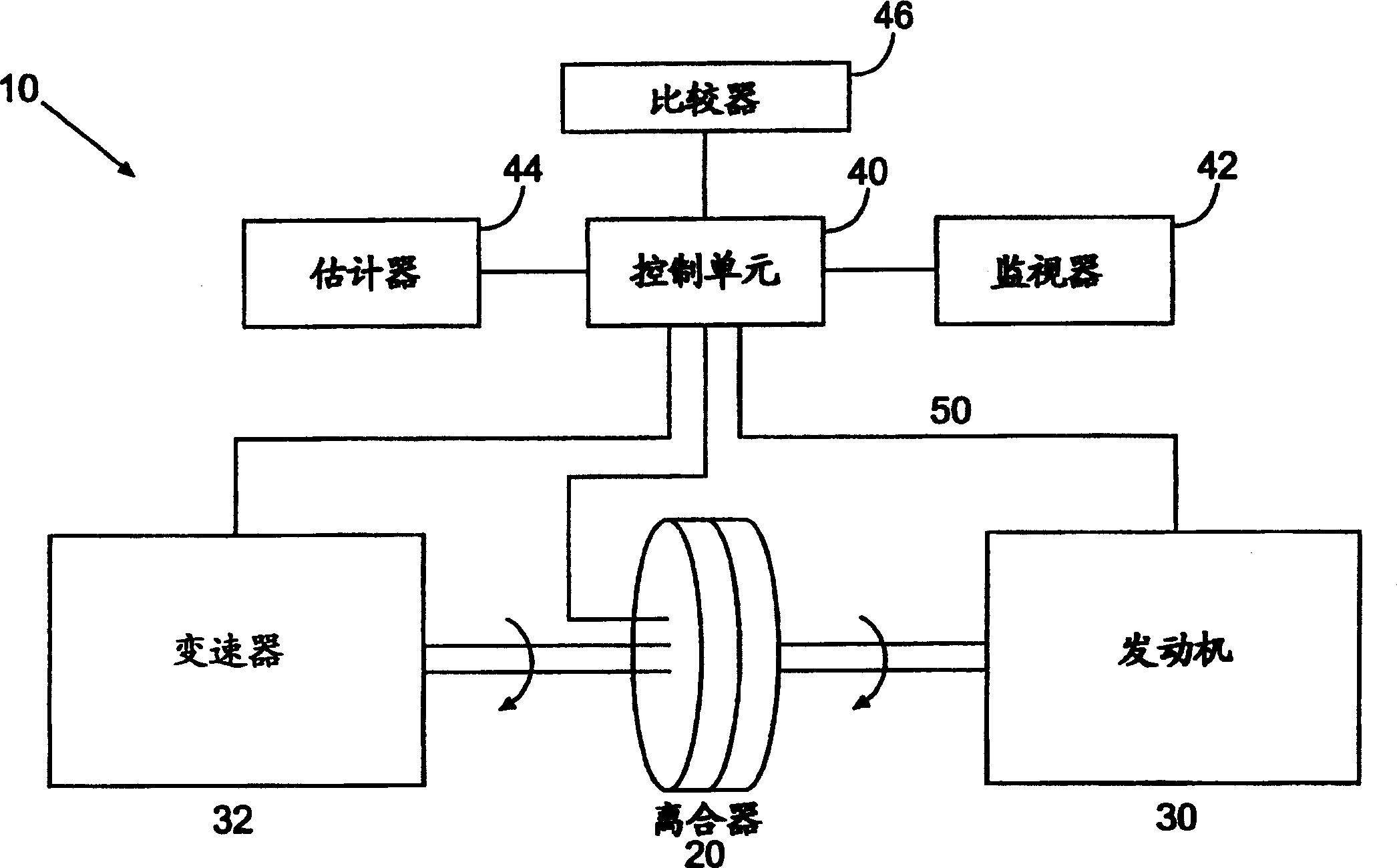
[0010] figure 1 A vehicle clutch protection system 10 according to one embodiment of the present invention is shown. Automatic transmission 32 is selectively engaged with engine 30 via clutch 20 . Transmission 32 may be any type of automatic transmission commonly used in vehicles, such as the Autoshift system manufactured by Eaton Corporation. Additionally, the transmission 32 may have the ability to be placed in a manual mode of operation, allowing the operator of the vehicle to determine when to actually shift the transmission 32 into another gear. Engine 30 may be any type of engine used to propel a vehicle. Typically this will be an internal combustion engine, although other types of engines such as electric motors could readily be used with the invention. Clutch 20 is a wet clutch that typically relies on oil, which acts not only as a lubricant but also as a coolant. Microprocessor based control unit 40 is connected to engine 30 , transmission 32 and clutch 20 via dat...


PUM


Abstract

A system (10) for protecting the clutch (20) of a vehicle from a harmful operating state. Included in the clutch protection system (10) are means for monitoring the operating state of the clutch, along with means for estimating the amount of energy being dissipated by the clutch (20). A control unit (40) compares the estimated amount of energy dissipated by the clutch (20) to one or more predetermined threshold energy levels. One or more actions designed to reduce the amount of energy dissipated by the clutch (20) are initiated when the estimated amount of energy dissipated by the clutch (20) exceeds the one or more predetermined thresholds.

Description

technical field [0001] The present invention relates to clutches for vehicles and, more particularly, to systems and methods for protecting clutches from excessive wear and damage. Background technique [0002] A clutch is a mechanical device designed to connect or disconnect power from one working part to another. In the case of a vehicle, the clutch is used to transfer power from the engine to the driveline and, when changing gears, to decouple the engine from the transmission. [0003] In its simplest form, a clutch can be thought of as consisting of two plates that can be selectively placed next to each other. A plate (flywheel) is attached to and rotated by the motor. The corresponding other plate (clutch plate) is connected to a transmission system (transmission system) to be operated by power of the engine. To transmit the engine's power to the gears, the clutch plates are pushed against the spinning flywheel. When pushed against each other, the two pieces initial...

Claims


Application Information

Patent Timeline
Patent Type & Authority Applications(China)
IPC IPC(8): F16D48/06
CPCY10T477/6395F16D48/06Y10T477/653Y10T477/6934F16D2500/31453F16D2500/5023F16D2500/50296F16D2500/7041F16D2500/70434F16D2500/7044F16D2500/70488F16D2500/7103F16D2500/7104B60W2050/143
Inventor W·J·麦克
Owner EATON INTELLIGENT POWER LTD
Why Eureka
Try Eureka