
System for monitoring resistance of electric fuse

An electric fuse and resistance technology, applied in the direction of measuring resistance/reactance/impedance, measuring electrical variables, emergency protection circuit devices for limiting overcurrent/overvoltage, etc., can solve identification difficulties, programming process and debugging difficulties And other issues

Active Publication Date: 2005-11-16
TAIWAN SEMICON MFG CO LTD
View PDF0 Cites 14 Cited by
  • Summary
  • Abstract
  • Description
  • Claims
  • Application Information

AI Technical Summary

Problems solved by technology

When it is desired to detect the resistance value of an electric fuse, since a single electric fuse is hidden in the macro of a large group of electric fuses, it is difficult to distinguish its resistance value at this time, so only its logic state can be checked
The programming process and debugging thus become difficult

Method used


Image

  • System for monitoring resistance of electric fuse
  • System for monitoring resistance of electric fuse
  • System for monitoring resistance of electric fuse

Examples


Embodiment Construction

[0038] The operation of the method and device of the present invention will be described in detail with specific examples and figures in the following implementation modes, so that readers can understand the convenience obtained by using the present invention.

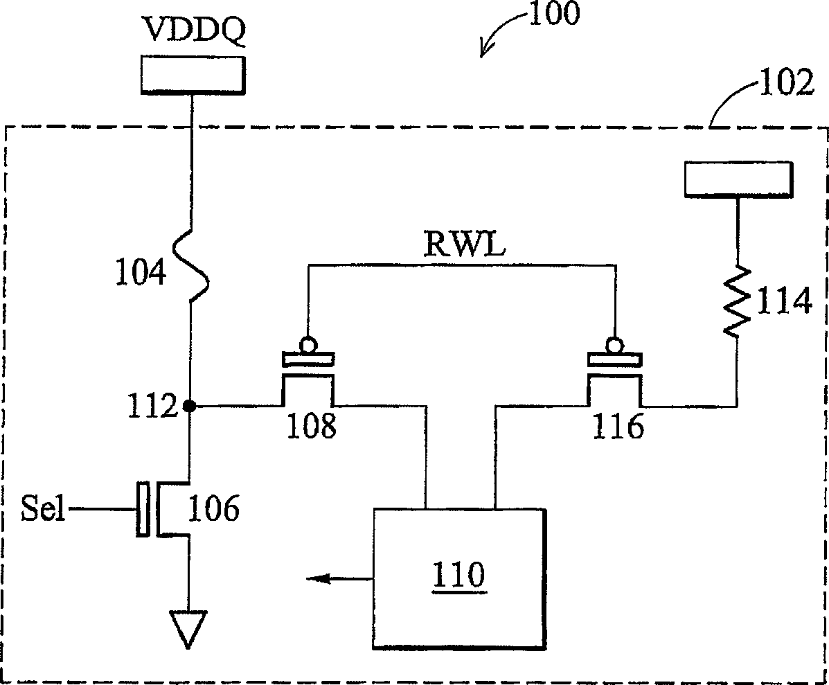
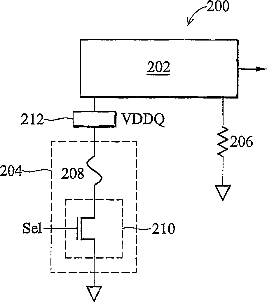
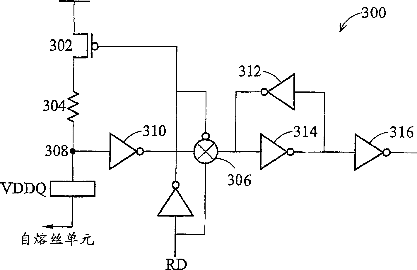
[0039] In the prior art, a fuse macro is formed by a plurality of fuse elements, and the fuse macro is called a fuse unit here. In order to monitor the fuse resistance value, a test circuit is built in the fuse macro so that an external tester can program and analyze the fuse unit. Unfortunately, it is difficult to distinguish the relationship between the external test circuit and a fuse element in the fuse macro, and the test circuit often occupies a large substrate area. The present invention provides a new type of circuit (on-chip fuse resistance monitoring and diagnosis circuit) that monitors the resistance of the fuse on the chip without additional testing circuit, so as to solve the problems in the prior art.

...


PUM


Abstract

A fuse resistance monitoring system is disclosed to comprise at least one non-regenerative sense amplifier; at least one fuse module having at least one fuse cell coupled to a first terminal of the sense amplifier; and a reference resistor coupled to a second terminal of the sense amplifier, wherein a source voltage node between the fuse module and the sense amplifier is monitored to reflect a resistance of the fuse cell.

Description

technical field [0001] This invention relates to the design of integrated circuits, and more particularly to methods for monitoring the resistance of electrical fuses on a wafer. Background technique [0002] Fuse elements are widely used in semiconductor memory elements. A plurality of fuse elements are generally used in a semiconductor memory device such as a dynamic random access memory (DRAM). Generally, each fuse element includes a selectively severable fuse to selectively separate the fuse element from the rest of the circuitry. The process of cutting a fuse is sometimes referred to as "blowing" the fuse. [0003] There are basically two techniques currently used to blow fuses. One method uses a laser to irradiate the fuse until the fuse blows; the other method blows the fuse by sending a sufficiently large "overcurrent" through the fuse. The process of blowing a fuse in a fuse element (the element usually includes at least one MOS transistor) is generally called "...

Claims


Application Information

Patent Timeline
Patent Type & Authority Applications(China)
IPC IPC(8): G01R27/02G11C17/16G11C17/18H01L27/02H01L29/00H01L29/74H02H9/00
CPCH01L29/7436G11C17/16G11C17/18H01L27/0262
Inventor 庄建祥陈云升
Owner TAIWAN SEMICON MFG CO LTD
Learn More