Gas breaker

A gas circuit breaker and gas technology, applied in the direction of high-voltage air circuit breakers, circuits, electrical components, etc., can solve the problems of difficult to adjust the addition rate of inorganic filler materials, promote heat diffusion, etc., to increase gas pressure, shorten insulation distance, improve The effect of arc extinguishing performance

Inactive Publication Date: 2005-11-23
JAPAN AE POWER SYST
View PDF3 Cites 11 Cited by
  • Summary
  • Abstract
  • Description
  • Claims
  • Application Information

AI Technical Summary

Problems solved by technology

[0005] However, as described in Japanese Patent Publication No. 1-45690 and Japanese Patent Publication No. 1-37822, the inorganic filler has high light reflectivity and high thermal conductiv

Method used


Image

  • Gas breaker
  • Gas breaker
  • Gas breaker

Examples


Embodiment

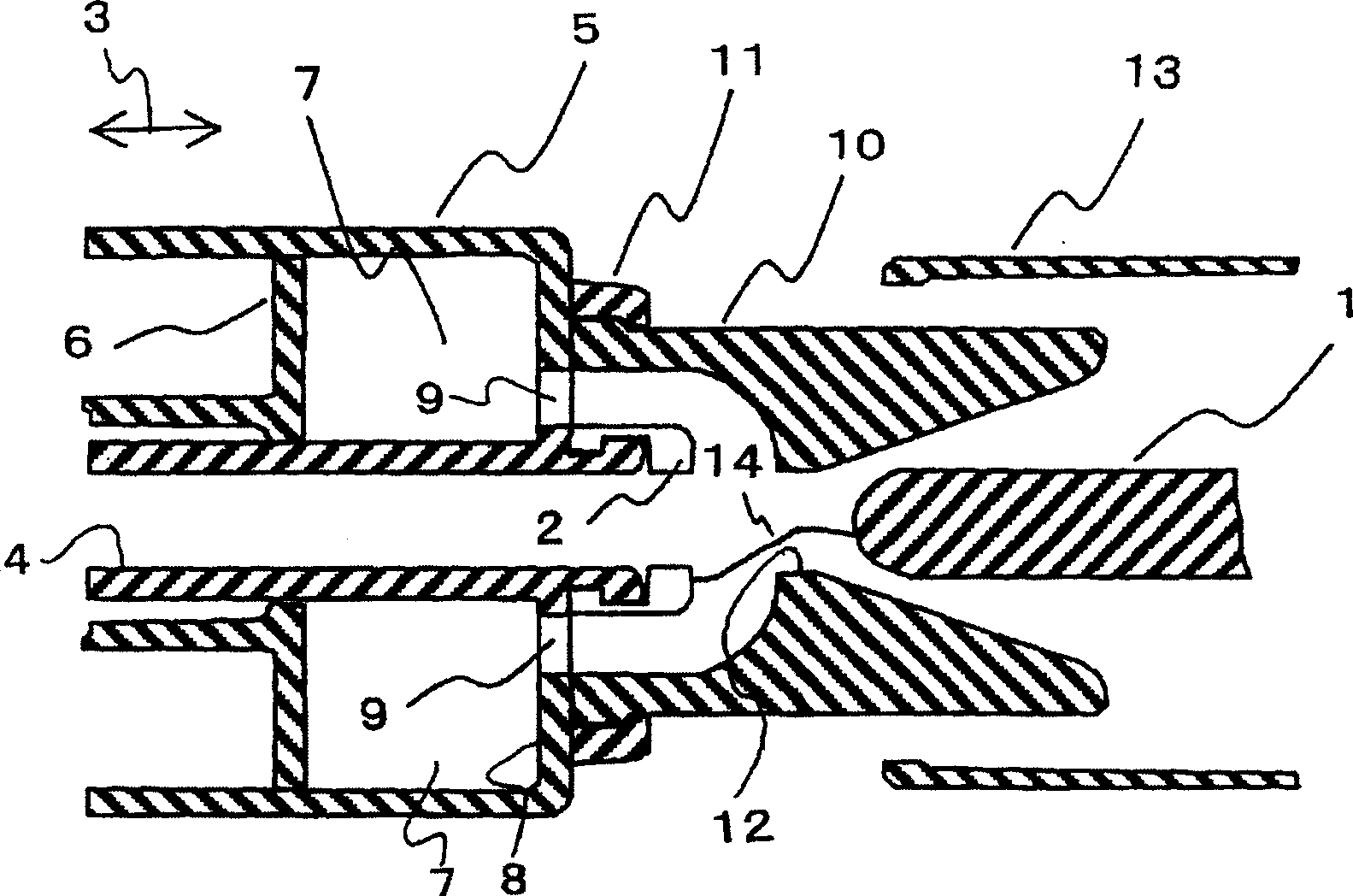
[0030] Here, the material of the nozzle 10 which is the characteristic of the present invention can be selected from the composite materials of Examples 1 to 8 shown in Table 1. According to these Examples, since the heat resistance and mechanical strength are excellent, the insulation recovery at the time of breaking is accelerated, and the arc voltage at the time of breaking is high, the breaking performance is remarkably improved. That is, it is possible to obtain a gas circuit breaker in which the breaking performance is remarkably improved by generating ablative gas.

[0031] Example

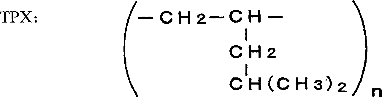
[0032] TPX: poly-4-methyl-1-pentene


PUM

PropertyMeasurementUnit
The average particle sizeaaaaaaaaaa

Abstract

The objective is to provide a gas circuit breaker improving an arc distinguishing performance. The gas circuit breaker is provided with: a fixed contactor 1 and a movable contactor 2 contactably and separably arranged in a container filled with an insulating gas; a tubular nozzle 10 installed surrounding the contact-separation parts of the fixed contactor and the movable contactor; and a buffer room 7 to compress the insulating gas and eject it into the nozzle while interlocked with the movable contactor. A nozzle 10 is formed by a composite material composed by adding an inorganic filler to a resin of lower heat resistance than that of a fluororesin, gas pressure inside the nozzle is elevated by an abrasion gas generated from the resin of lower heat resistance than that of the fluororesin by arc energy, and the arc distinguishing performance is improved.

Description

technical field [0001] FIELD OF THE INVENTION This invention relates to gas circuit breakers, and more particularly, to materials for arc blow-off nozzles that provide improved breaking performance. Background technique [0002] A gas circuit breaker is a device that cuts off a large current such as a short circuit current. It is formed by arranging the static contact and the moving contact of the intermittent current on the coaxial line so that they can be broken and closed, and storing them in a container filled with insulating gas. constitute. In particular, the buffer type gas circuit breaker has been disclosed as follows: when the static contact and the moving contact are disconnected, in order to quickly blow off the arc generated between them, a device is provided to surround the breaking position of the static contact and the moving contact. The cylindrical nozzle in the space introduces compressed gas into the nozzle, and sprays it to the breaking and closing parts...

Claims


Application Information

Patent Timeline
IPC IPC(8): H01H33/70H01H33/02H01H33/91
Inventor 师冈寿至竹泽由高白石胜彦浦井一大下阳一
Owner JAPAN AE POWER SYST
Why Eureka
Try Eureka