Organic el display

An electroluminescent display and electroluminescent layer technology, which is applied to electroluminescent light sources, electric light sources, instruments, etc., can solve the problems of reduced light efficiency, reduced contrast between light and shadow, etc.

Active Publication Date: 2005-12-14
LG DISPLAY CO LTD
View PDF2 Cites 10 Cited by
  • Summary
  • Abstract
  • Description
  • Claims
  • Application Information

AI Technical Summary

Problems solved by technology

[0007] However, since external light such as outdoor sunlight, indoor lighting light, etc. is reflected on the cathode of the OLED display through the OLED surface, the contrast between light and shadow decreases in conventional OLED displays.
[0008] In addition, although conventional organic electroluminescent displays employ various polarizers to prevent a decrease in contrast, light efficiency decreases because light emitted from the organic electroluminescent display is partially absorbed through the polarizers.

Method used


Image

  • Organic el display
  • Organic el display
  • Organic el display

Examples


Embodiment Construction

[0031] Reference will now be made in detail to the preferred embodiments of the present invention, examples of which are illustrated in the accompanying drawings. Where possible the same reference numbers will be used throughout the drawings to refer to the same or like parts.

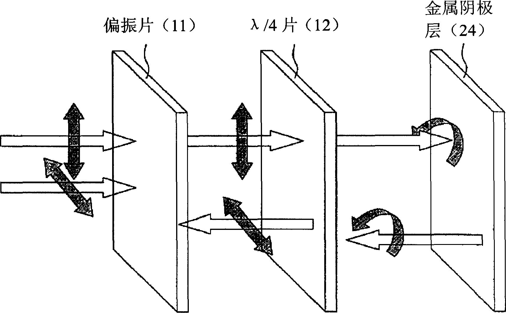
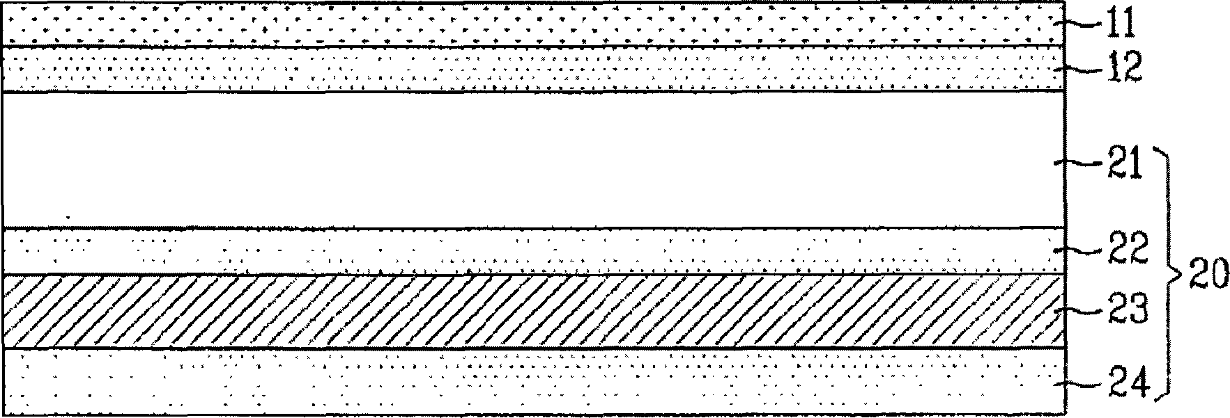
[0032] figure 1 is a schematic diagram for illustrating the polarization principle of the organic electroluminescent display according to the present invention, and figure 2 is a cross-sectional view of an organic electroluminescence display according to the present invention.

[0033] refer to figure 1 and figure 2 , in the organic electroluminescent display according to the present invention, the organic electroluminescent display panel 20 includes a substrate 21, an anode 22 on one surface of the substrate, an organic electroluminescent layer 23 on the anode 22, an organic electroluminescent Cathode 24 on layer 23 , first polarizer 12 on the other surface of substrate 21 , and second polarizer...


PUM


Abstract

The invention discloses an organic EL display having a polarizing plate. The present invention includes an organic EL display panel, a first polarizing plate on the panel to convert a circularly or linearly polarized light to a linearly or circularly polarized light, and a second polarizing plate on the first polarizing plate to have a polarization characteristic of absorbing light in a high light efficiency wavelength range more than light in a low light efficiency wavelength range.

Description

[0001] This application claims the benefit of Korean Patent Application No. 10-2004-0034857 filed on May 17, 2004 and Korean Patent Application No. 10-2004-0070852 filed on September 6, 2004, the entire contents of which are incorporated in This is for reference. technical field [0002] The present invention relates to an organic electroluminescent display, in particular to an organic electroluminescent display with a polarizer. Background technique [0003] Generally, current-driven flat panel displays include LCD (Liquid Crystal Display), PDP (Plasma Display), VFD (Visible Fluorescent Display), FED (Electroluminescence Display), LED (Light Emitting Diode), EL (Electroluminescence), etc. , developed significantly over the decades most commonly used CRT (Cathode Ray Tube). [0004] The current-driven display device has high visibility and good chromaticity, and its manufacturing process is simple. Therefore, the current-driven display device is expanding its application f...

Claims


Application Information

Patent Timeline
Patent Type & Authority Applications(China)
IPC IPC(8): G02F1/1335H05B33/12
CPCA01K93/02
Inventor 崔哄硕
Owner LG DISPLAY CO LTD
Why Eureka
Try Eureka