
A walking type bicycle

A bicycle and frame technology, applied in the field of reciprocating pedal bicycles, can solve the problems of high risk, human fatigue, wear and tear, etc., and achieve the effects of high efficiency and frequency, wide application and high transmission efficiency

Inactive Publication Date: 2005-12-21
谭干棠
View PDF11 Cites 4 Cited by
  • Summary
  • Abstract
  • Description
  • Claims
  • Application Information

AI Technical Summary

Problems solved by technology

[0004] Bicycle belongs to a kind of simple walking-replacing machine, and through hundreds of years of development, although the technology is very mature and stable, it is difficult to make a major breakthrough in technology, but the bicycles currently available in the market have the following disadvantages: 1) mostly adopt pedal circle The driving mode is equivalent to a person doing long-span running. The exercise is intense, the muscles are highly contracted, the energy consumption is huge, and people are easily fatigued.
2) The pedal handle is short and the effective moment arm is short
3) Due to the circular motion of the pedals, the effective force arm changes cyclically from: zero---maximum---zero---(counting from the pedals being vertical), there will be "dead points" and "blind spots" "Appears, poor continuous exertion, small useful effect
4) poor security and stability
7) It is extremely dangerous when the tire is punctured or leaks during driving
However, due to the special supporting position and structure of the rocker arm, the device must adopt a reset mechanism to help the left and right two fan-shaped active meshing wheels and the rocker arm to realize the alternation of the upper and lower positions, and the reset mechanism is a steel wire sleeve (wire Pull rope), obviously, such a steel wire will be easily worn by the outer casing under frequent and forceful pulling during riding, and the efficiency and practicability of the reset transmission are very low

Method used


Image

  • A walking type bicycle
  • A walking type bicycle
  • A walking type bicycle

Examples


Embodiment 1

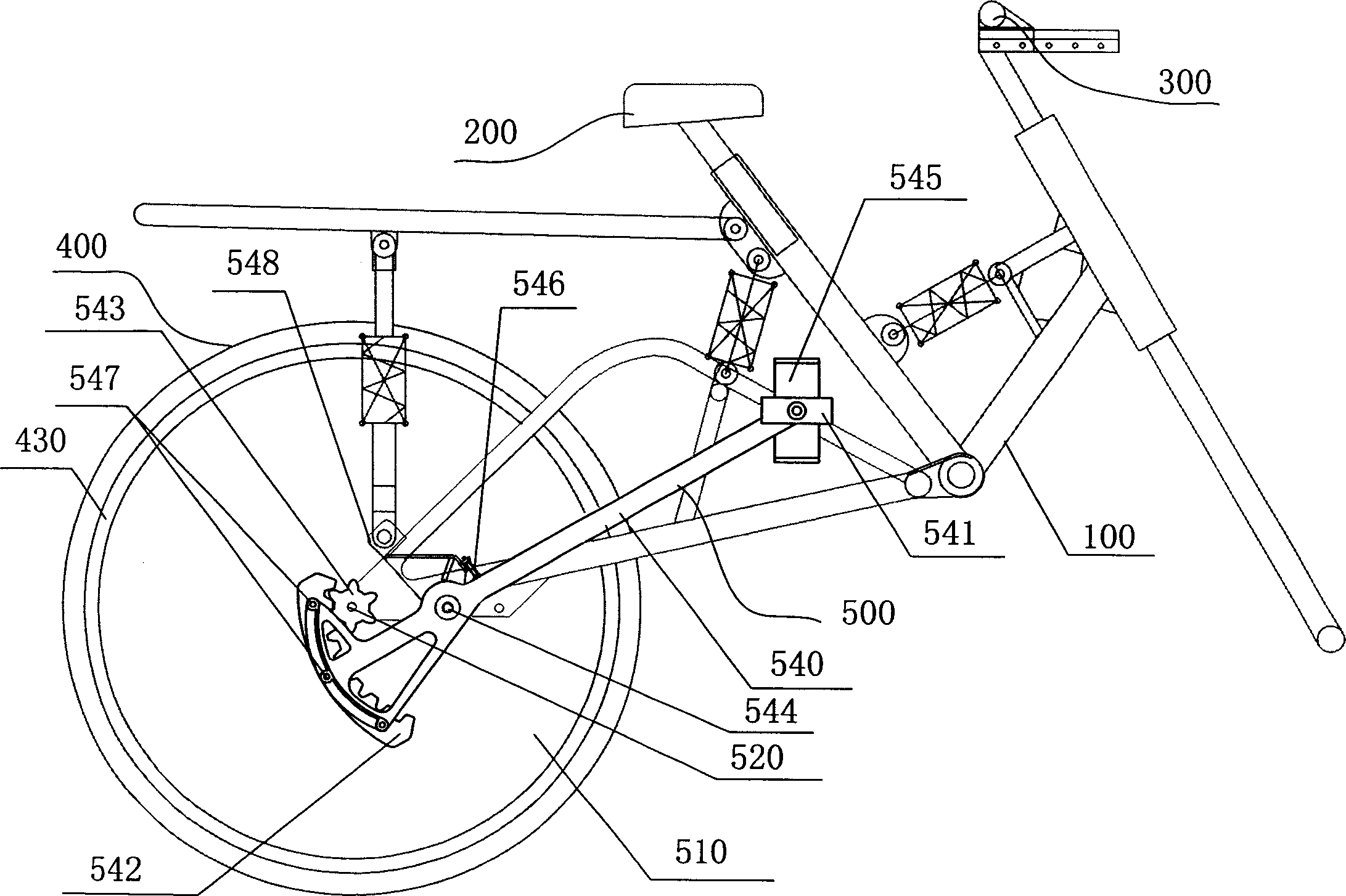
[0074] like figure 1 Shown is a reciprocating pedaling drive device 500 of a reciprocating pedal bicycle, which includes a rear wheel 510 for driving and a rear wheel shaft 520, the rear wheel 510 for driving has the same rim 430 and tire 400 as the front wheel, and the vehicle frame The left and right sides of 100 are respectively provided with a pedal handle 540 (only one of them is shown), a pedal 541 fixed on the pedal handle 540 and a sector-shaped active meshing wheel 542 of an internal ring gear structure, which are actively engaged with the sector. The one-way flywheel 543 of the band meshing tooth that wheel 542 meshes, and pedal 541 is fixed on the front end of pedal handle 540, and fan-shaped active meshing wheel 542 is fixed on the 540 rear ends of pedal handle, between the two ends of pedal handle 540 There is a pin hole on the handle body of the vehicle frame 100, and a handle pin 544 is connected to the vehicle frame 100. The pedal handle 540 is hinged on one si...

Embodiment 2

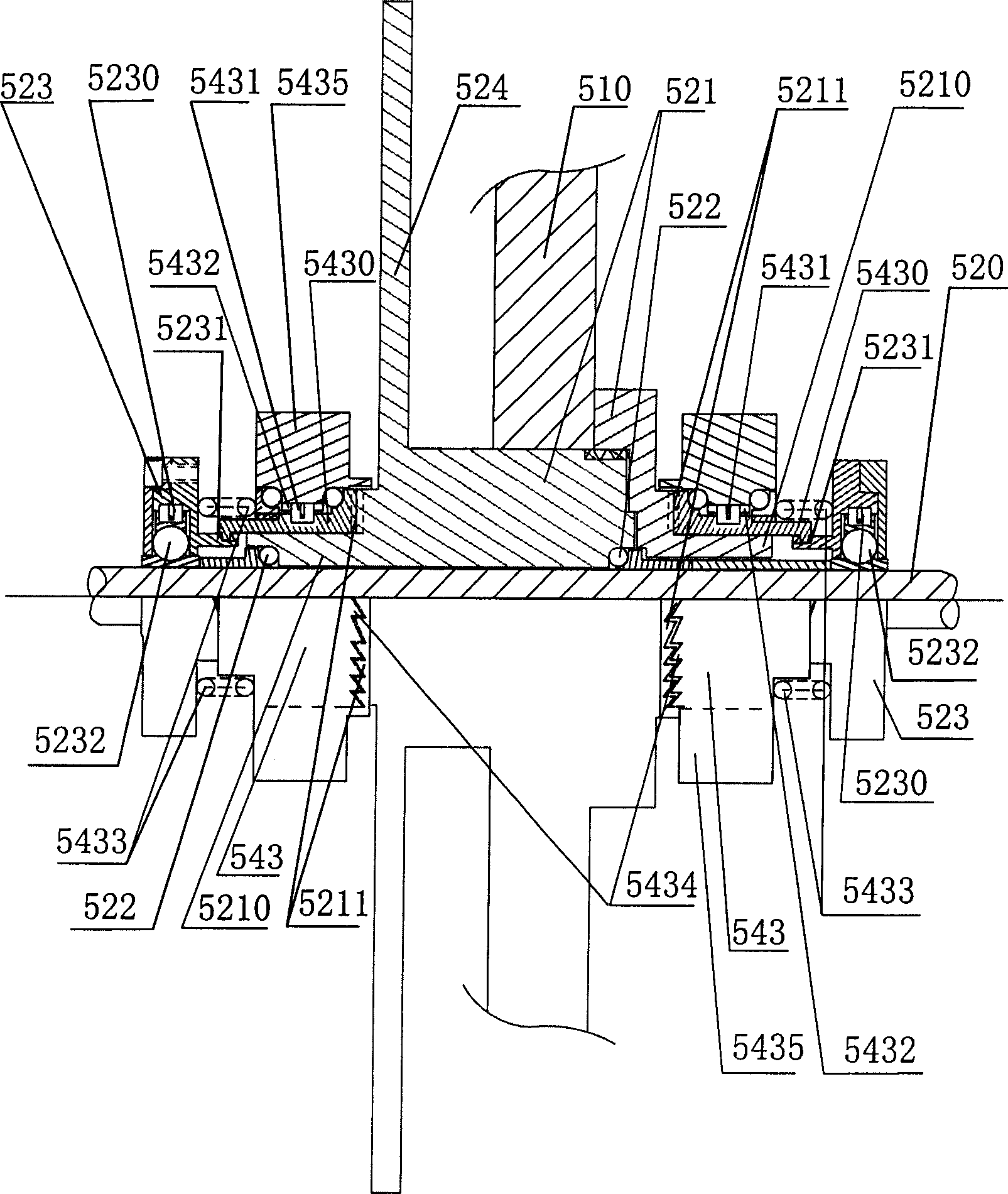
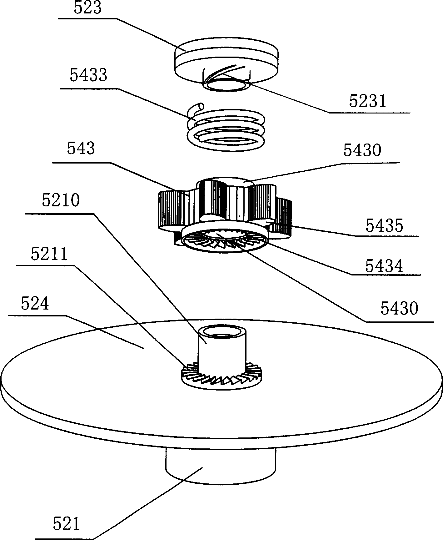
[0077] like figure 2 , 3 , shown as a two-stage series-connected gear-type pedaling one-way driver of the reciprocating pedaling drive device 500, which includes a one-way driving driving roller 521 directly fixed to the center of the rear wheel 510, and the left and right ends of the driving roller 521 A wheel shaft sleeve 5210 is fixedly connected to the top, and a rolling bearing 522 is arranged between the wheel shaft sleeve 5210 and the rear wheel shaft 520. A brake disc 524 is fixedly connected to one side of the driving roller 521; Gear 5211; left and right two one-way flywheels 543 include outer ring gear 5435 and traditional one-way ratchet mechanism-comprising ratchet ring 5432 on the outer ring surface of one-way flywheel 543 and one-way flywheel 543 The elastic ratchets 5431 on the inner ring 5430 are respectively movably matched with the inner ring 5430 on the hub 5210 on the same side. In addition, the one-way flywheels 543 on both sides are provided with the o...

Embodiment 3

[0081] like Figure 4, shown as a two-stage series-connected sprocket type pedaling unidirectional driver of the reciprocating pedaling drive device 500, since the sector-shaped active meshing wheel 542 can also be an inner arc chain segment structure (not shown in detail), therefore, with the inner arc chain segment The one-way flywheel 543 of the sprocket outer ring type and the pedal one-way driver are engaged with the meshing wheel 542, which includes a one-way drive driving roller 521 directly affixed to the center of the rear wheel 510. The driving roller 521 has two left and right sides. A wheel shaft sleeve 5210 is fixedly connected to the end, a rolling bearing 522 is arranged between the wheel shaft sleeve 5210 and the rear wheel shaft 520, and a brake disc 524 is fixedly connected to one side of the driving roller 521; Ratchet gear 5211; left and right two one-way flywheels 543 include outer ring sprocket 5435' and traditional one-way ratchet mechanism-comprising ra...


PUM


Abstract

The invention relates to a bicycle of the ambulation style. It contains the frame of the bicycle, the braking mechanism, the back annulus for driving, the back-annulus axes, the tyre, the footplate is fixed on the stepping handle, the fan-shaped main gear wheel and the unilateralism flywheel with the gear wheel. The left and right sides of the frame of the bicycle sets up a stepping handle and its footplate, the gear wheel and the unilateralism flywheel. The footplate is fixed in the front of the stepping handle and the gear wheel is fixed in the back of the stepping handle. The handle body between two ends of the stepping handle has the pinhole and the handle pin connects on the frame of the bicycle and hinge-joints on the frame of the bicycle by the pinhole and the handle pin. The outer circle of the unilateralism flywheel is the gear or the chain wheel. The footplate connects on the gear wheel. On the one side of the footplate are set up with the side-hamulus. The invention is easy and applied. It has the deft organization, the high efficiency transmission, the comfortable riding, the quakeproof and the defending bursting-tyre.

Description

【Technical field】 [0001] The present invention relates to a walking bicycle, and more particularly, the present invention relates to a reciprocating pedal bicycle. 【Background technique】 [0002] Bicycles are widely adopted by families and individuals in China because of their economy, convenience, flexibility, pollution-free, and free parking. Although with the improvement of people's lives, mainstream means of transportation and machinery are constantly being upgraded: from bicycles to buses, from buses to motorcycles, and then from motorcycles to private cars... This development trend is in the ascendant, but with it The social, natural, and economic problems such as energy shortage, environmental pollution, and traffic congestion that come with it are also becoming a strong resistance to restricting this development trend. It can be predicted that in the next few decades, no matter in China's urban or rural areas, the vast majority of the population will still use bicyc...

Claims


Application Information

Patent Timeline
Patent Type & Authority Applications(China)
IPC IPC(8): B62K3/00B62M1/24
Inventor 谭乾棠
Owner 谭干棠
Learn More