Adjustable wireless charging system

A wireless charging and capacitor technology, applied in charging stations, electric vehicle charging technology, electric vehicles, etc., can solve the problems of complex harmonic composition and large electromagnetic compatibility, and achieve the effects of low interference noise, reduced interference, and high-efficiency transmission

Pending Publication Date: 2020-12-18
BEIJING INVISPOWER TECH CO LTD
View PDF1 Cites 4 Cited by
  • Summary
  • Abstract
  • Description
  • Claims
  • Application Information

AI Technical Summary

Problems solved by technology

[0003] Patent CN110126648A "Self-optimized tuning control method for electric vehicle wireless charging maximum current tracking" proposes a method of adjusting the operating frequency of the inverter to obtain the maximum output current through frequency conversion control, because the frequency conversion adjustment will make the voltage and current contain Abundant high-order harmonics, and the composition of the harmonics is very complex due to the frequent adjustment of the operating frequency. The electromagnetic noise energy of these harmonics will form electromagnetic interference through circuit connection or electromagnetic wave space coupling, which will cause great damage to the system itself and the surrounding environment. EMC problems

Method used


Image

  • Adjustable wireless charging system
  • Adjustable wireless charging system
  • Adjustable wireless charging system

Examples


Embodiment Construction

[0021] Embodiments of the present invention are described in detail below, examples of which are shown in the drawings, wherein the same or similar reference numerals designate the same or similar elements or elements having the same or similar functions throughout. The embodiments described below by referring to the figures are exemplary only for explaining the present invention and should not be construed as limiting the present invention.

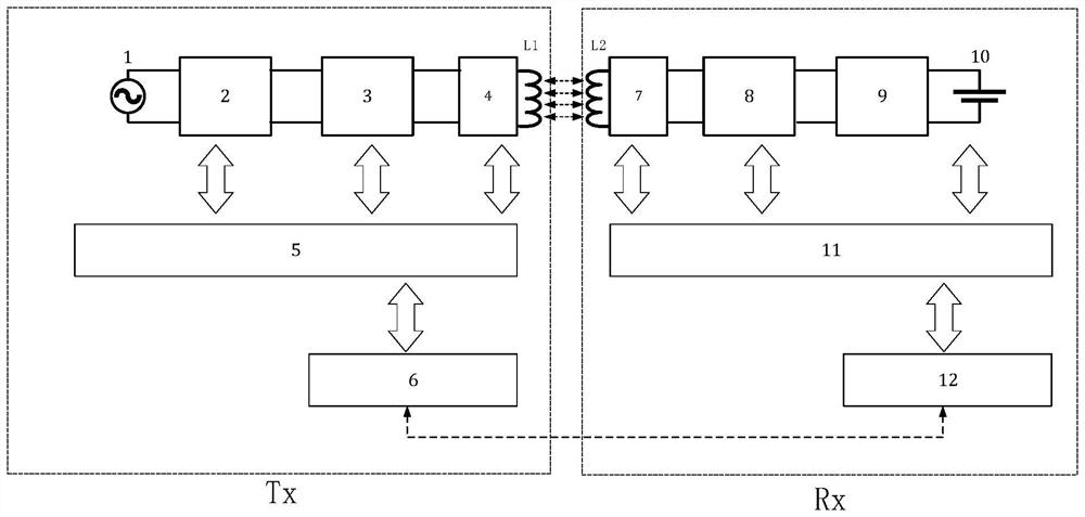
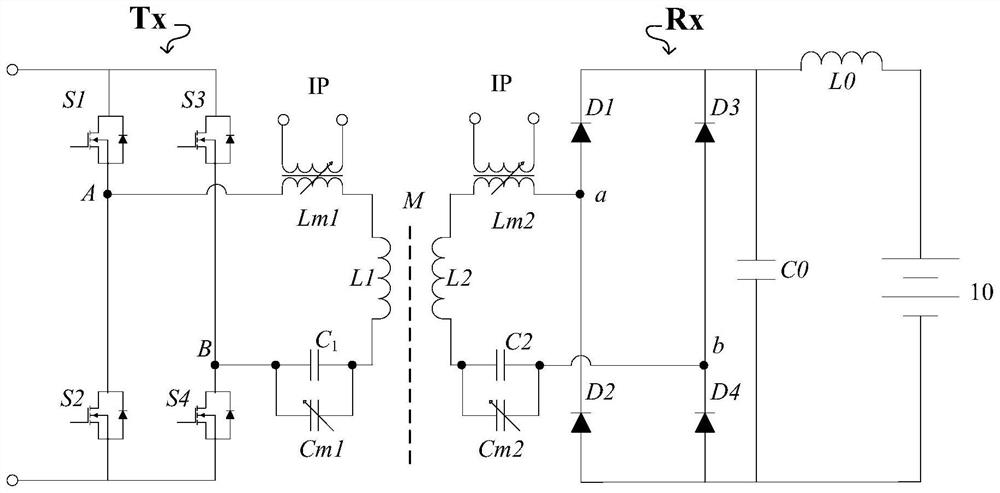
[0022] see figure 1 and figure 2 , the adjustable wireless charging system of the present invention has a transmitting end Tx and a receiving end Rx. The transmitter Tx converts the power-frequency alternating current provided by the power source 1 into direct current after rectification and power factor adjustment by the direct current converter 2 . The direct current is then converted into high-frequency alternating current by the inverter 3 . The high-frequency alternating current passes through the resonant network 4 at the trans...


PUM


Abstract

The invention discloses an adjustable wireless charging system which is divided into a transmitting end and a receiving end, the transmitting end is provided with a transmitting end resonance network,the transmitting end resonance network at least comprises a transmitting coil and a first capacitor, the receiving end is provided with a receiving end resonance network, and the receiving end resonance network at least comprises a receiving coil and a second capacitor. The system further comprises correction devices which are respectively a transmitting end correction capacitor, a receiving endcorrection capacitor, a transmitting end correction inductor and a receiving end correction inductor; the transmitting end correction capacitor is connected with the first capacitor in parallel and provides a variable capacitance value for the transmitting end; the receiving end correction capacitor is connected with the second capacitor in parallel and provides a variable capacitance value for the receiving end; the transmitting end correction inductor is connected with the transmitting coil in series and provides a variable inductance value for the transmitting end; the receiving end correction inductor is connected with the receiving coil in series and provides a variable inductance value for the receiving end; the driving frequency of an input source of the transmitting end resonance network, the resonance frequency of the transmitting end resonance network and the resonance frequency of the receiving end resonance network are all 79kHz-90kHz. According to the adjustable wireless charging system, the total capacitance value or the total inductance value of the transmitting end resonance network and the receiving end resonance network is adjusted through the correction devices,so that the resonance stability is ensured, the interference of an environmental electromagnetic field is reduced, and the maximum efficiency transmission and the minimum interference noise are obtained.

Description

technical field [0001] The invention relates to the field of wireless charging, in particular to an adjustable wireless charging system. Background technique [0002] Wireless charging is a non-contact energy transmission method, which can realize the safe and efficient use of energy. Especially for electric vehicles with automatic driving and automatic parking, wireless charging can effectively support the whole process of unmanned operation of the vehicle. It is a new energy An important direction of automobile development. The wireless transmission of electric energy is realized by exciting the alternating electromagnetic field. In order to obtain greater power transmission, it is necessary to increase the strength of the electromagnetic field; on the other hand, because the electromagnetic field energy is excited in an open space, wireless charging will inevitably involve Electromagnetic compatibility (EMC) issues. [0003] Patent CN110126648A "Self-optimized tuning co...

Claims


Application Information

Patent Timeline
Patent Type & Authority Applications(China)
IPC IPC(8): H02J50/12H02J50/70B60L53/12
CPCB60L53/12H02J50/12H02J50/70Y02T10/70Y02T10/7072Y02T90/14
Inventor 王哲陆钧贺凡波葛俊杰马俊超
Owner BEIJING INVISPOWER TECH CO LTD
Why Eureka
Try Eureka