

Method for manufacturing lock shaft parts for container
A technology for containers and locks, applied in building locks, building structures, buildings, etc., to achieve the effects of adapting to large-scale production, significant technological advancement, and reducing production costs
- Summary
- Abstract
- Description
- Claims
- Application Information
AI Technical Summary
Problems solved by technology
Method used
Image

Examples
Embodiment 1
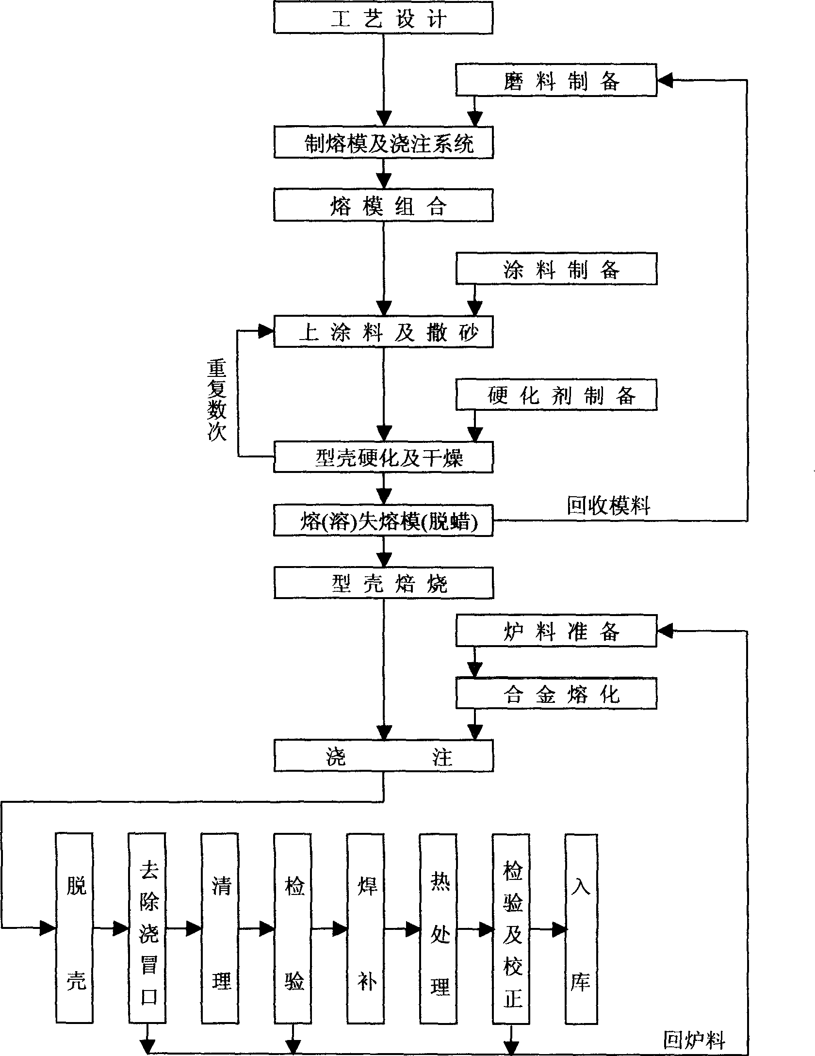
[0050] a. Wax model making;
[0051] According to the structure of casting parts, design the pouring riser system. The wax mold has a reasonable pouring system design, which can ensure the sequential solidification of the castings; it can be poured in multiple layers with columnar risers. It can also be poured in a single layer with a spherical riser. The gate can be single gate or double gate.
[0052] b. Shell molding;
[0053] Using water glass as a binder to make the shell mold, including hardening, dewaxing and roasting of the shell mold.
[0054] c. Prepare a high-strength alloy material whose composition is:
[0055] C: 0.38 Si: 0.33 Mn: 0.94
[0056] Cr: 1.09 Mo: 0.27 S, P≤0.025;
[0057] d. Melting and pouring of alloy materials:
[0058] It adopts intermediate frequency furnace melting, adopts non-oxidizing steelmaking process, and selects rare earth ferrosilicon (FeSiRe45) for deoxidation,
[0059] Melting temperature: 1590°C; casting pouring, pouring temper...
PUM
 Abstract
Description
Claims
Application Information