Electrolytic capacitor

A technology of electrolytic capacitors and capacitors, which is applied in the direction of electrolytic capacitors, capacitors, capacitor parts, etc., and can solve the problems of low impedance characteristics, low moisture resistance of electrolytic capacitors, and inability to meet high withstand voltage.

Inactive Publication Date: 2005-12-21
NIPPON CHIMI CON CORP +1
View PDF1 Cites 0 Cited by
  • Summary
  • Abstract
  • Description
  • Claims
  • Application Information

AI Technical Summary

Problems solved by technology

[0007] However, the above-mentioned electrolytic capacitors cannot cope with such low impedance characteristics, and the upper limit of the withstand voltage is 30V. Although it can handle 28V, it cannot meet the high withstand voltage requirement of 84V or more.
In addition, such electrolytic capacitors are also required to have the same moisture resistance as semiconductors, and the moisture resistance of the above-mentioned electrolytic capacitors is also low, which is a problem.

Method used


Image

  • Electrolytic capacitor
  • Electrolytic capacitor

Examples


Embodiment

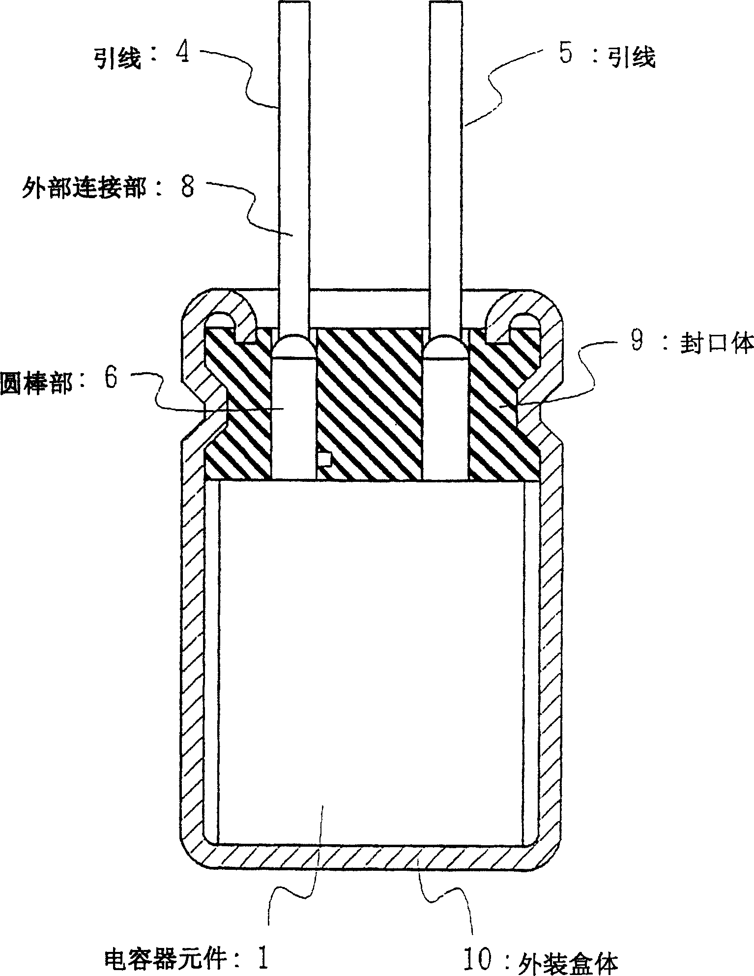
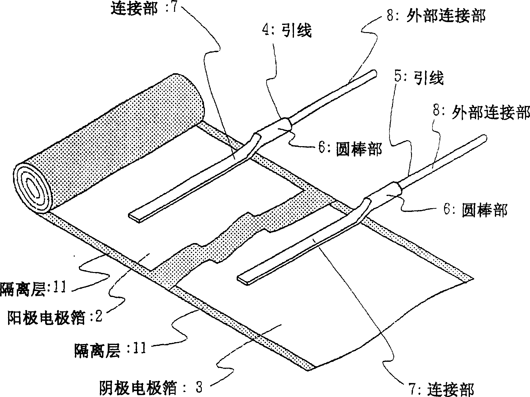
[0034] Next, the first invention will be described using examples. The construction of the electrolytic capacitor is the same as before, refer to figure 1 , figure 2 Be explained. The capacitor element 1 is formed by rolling an anode electrode foil 2 and a cathode electrode foil 3 with a separator 11 interposed therebetween. Also, if figure 2 As shown, the anode electrode foil 2 and the cathode electrode foil 3 are connected to the lead wire 4 for drawing out the anode and the lead wire 5 for drawing out the cathode, respectively.

[0035] These lead wires 4 and 5 are composed of a connection part 7 in contact with each foil, a round bar part 6 integrally formed with the connection part 7 , and an external connection part 8 bonded to the tip of the round bar part 6 . In addition, the connection part 7 and the round bar part 6 are made of 99% aluminum, and the external connection part 8 is made of copper-plated iron wire (hereinafter referred to as CP wire). On at least ...


PUM


Abstract

The present invention provides an electrolytic capacitor having low impedance characteristics, high withstand voltage characteristics of 100 V class, and excellent moisture resistance and high temperature life characteristics. As the isolation layer, an isolation layer made of heat-resistant synthetic resin such as polyester, polypropylene, polyethylene, polyamide, vinylon, rayon or mixed paper containing glass fiber is used, so it has low impedance characteristics, high It is also good in withstand voltage characteristics, moisture resistance, and high temperature life characteristics.

Description

technical field [0001] The present invention relates to electrolytic capacitors, and more particularly to electrolytic capacitors having low impedance characteristics and high withstand voltage characteristics. technical background [0002] Electrolytic capacitors are generally figure 1 construction shown. That is, the anode electrode foil 2 and the cathode electrode foil 3 are rolled up with a separator 11 made of manila paper to form a capacitor element 1, wherein the strip-shaped high-purity aluminum foil is chemically or electrochemically etched to make the surface of the aluminum foil Expand, and perform chemical conversion treatment on the aluminum foil in a chemical conversion solution such as ammonium borate aqueous solution to form an oxide film layer on the surface as the anode electrode foil 2; only perform etching treatment on the high-purity aluminum foil as the cathode electrode foil 3. Then, the capacitor element 1 is housed in a bottomed cylindrical outer c...

Claims


Application Information

Patent Timeline
Patent Type & Authority Applications(China)
IPC IPC(8): H01G9/035H01G9/10
Inventor 小泽正武田政幸宇惠诚
Owner NIPPON CHIMI CON CORP
Why Eureka
Try Eureka