Low voltage annular oscillator with almost constant delay time

A ring oscillator, delay time technology, used in power oscillators, electrical pulse generator circuits, electrical components, etc.

Inactive Publication Date: 2005-12-28
ETRON TECH INC
View PDF2 Cites 23 Cited by
  • Summary
  • Abstract
  • Description
  • Claims
  • Application Information

AI Technical Summary

Problems solved by technology
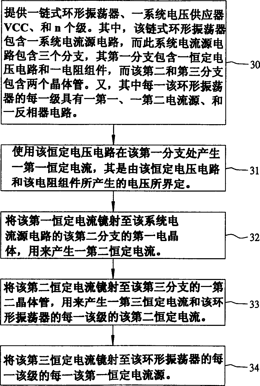
[0016] Therefore, if figure 1 As shown, the known ring oscillator can only operate accurately when the voltage difference I1×R1 is much larger than the sum of the threshold voltage |VTHP1|+VTHN1

Method used


Image

  • Low voltage annular oscillator with almost constant delay time
  • Low voltage annular oscillator with almost constant delay time
  • Low voltage annular oscillator with almost constant delay time

Examples


Embodiment Construction

[0034] The preferred embodiments disclose methods and circuits for a Complementary Metal Oxide Semiconductor (CMOS) with a constant delay time across temperature and semiconductor process variations.

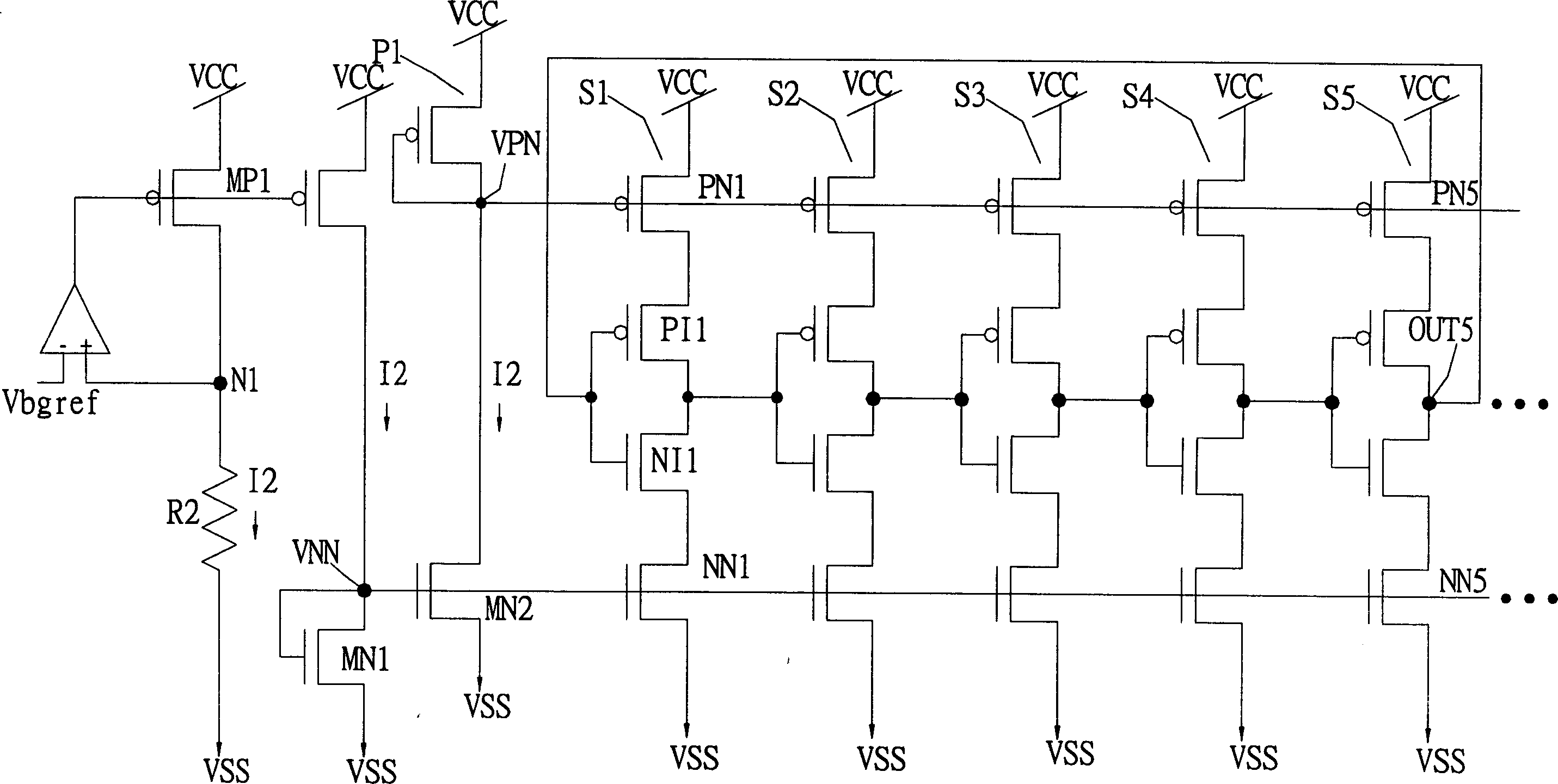
[0035] figure 2 A circuit diagram of a preferred embodiment of a chain-link ring oscillator of the present invention is shown.

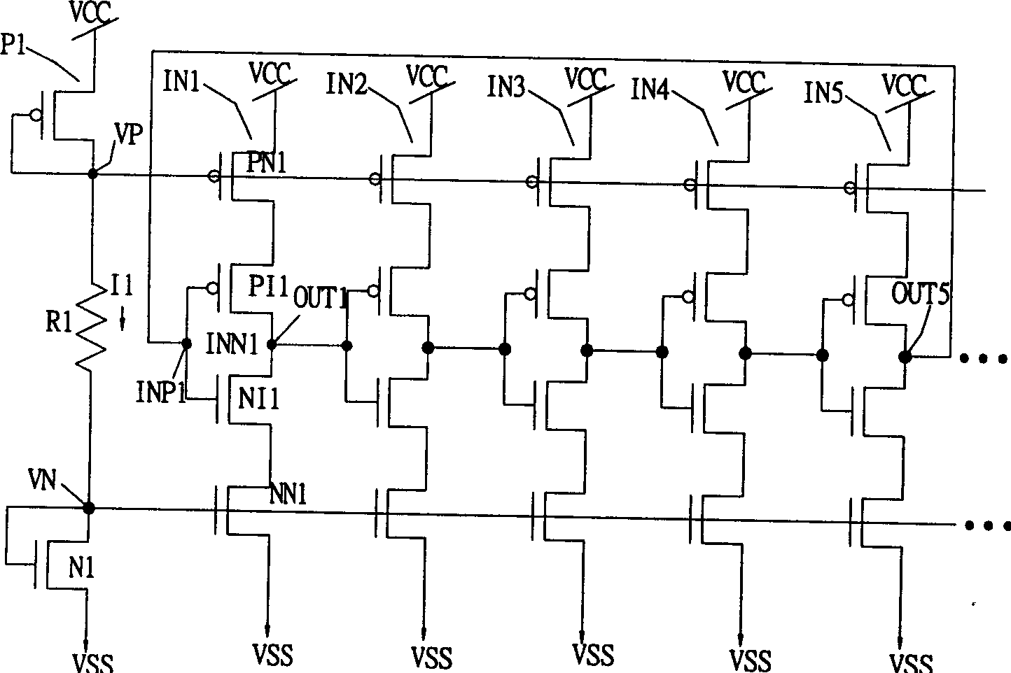
[0036] The preferred embodiment shows a ring oscillator with five stages of inverters S1 to S5. We can clearly see that, figure 2 The ring oscillator in is an unlimited example. The present invention supports any ring oscillator with an odd number (3, 5, 7, etc.) of stages of inverters.

[0037] The feature of the invention is that it has a constant system current source in different temperatures and different processes. exist figure 2 In the preferred embodiment shown in , a constant system current source is provided using a constant voltage circuit. The constant voltage circuit is based on the bandgap value Vbgref of a semiconductor, which i...


PUM


Abstract

The present invention relates to a method and circuit requiring only low voltage operation for a chained ring oscillator having a constant delay time across temperature and semiconductor process variations. A system current source includes a constant voltage circuit to generate a constant voltage and thus a constant current through a resistor element. The main parts of the constant voltage circuit are an operational amplifier and a bandgap reference circuit. Using a series of current mirrors, this constant current is mirrored to the current sources contained in the n-stage inverters of each chained ring oscillator.

Description

technical field [0001] FIELD OF THE INVENTION The present invention relates to a ring oscillator circuit, and more particularly, to a ring oscillator circuit having an almost constant delay time even if the operating voltage suddenly drops. Background technique [0002] Ring oscillators are used for a variety of different purposes. Usually the ring oscillator is used as an internally generated clocking source (internally generated clocking source) or in a more complex system: such as a voltage controlled oscillator (voltage controlled oscillator, VCO) or a phase-locked loop (phase locked loop, PLL) as a stage. They are often used to issue an updated command for memory devices such as dynamic random access memory (DRAM). [0003] For applications such as memory circuit design, circuits with constant delay are important. [0004] figure 1 is a known circuit diagram of a chained ring oscillator with five stages of CMOS (complementary metal-oxide-semiconductor) inverters. U...

Claims


Application Information

Patent Timeline
Patent Type & Authority Applications(China)
IPC IPC(8): H03B5/04H03K3/011H03K3/03
CPCH03K3/011H03K3/0315
Inventor 许人寿
Owner ETRON TECH INC
Why Eureka
Try Eureka