
Reciprocating compressor for compressing refrigerant

A compression refrigeration and reciprocating technology, applied in the direction of liquid variable displacement machinery, mechanical equipment, machines/engines, etc., can solve the problems of refrigerant heat transfer performance and lubrication performance degradation, wear of friction parts, damaged parts, etc.

Inactive Publication Date: 2005-12-28
LG ELECTRONICS INC
View PDF0 Cites 5 Cited by
  • Summary
  • Abstract
  • Description
  • Claims
  • Application Information

AI Technical Summary

Problems solved by technology

Then, the deterioration of the oil circulation degrades the heat transfer performance and lubricating performance of the refrigerant, causing the friction parts of each moving part to wear and thus damage the parts

Method used


Image

  • Reciprocating compressor for compressing refrigerant
  • Reciprocating compressor for compressing refrigerant

Examples


Embodiment Construction

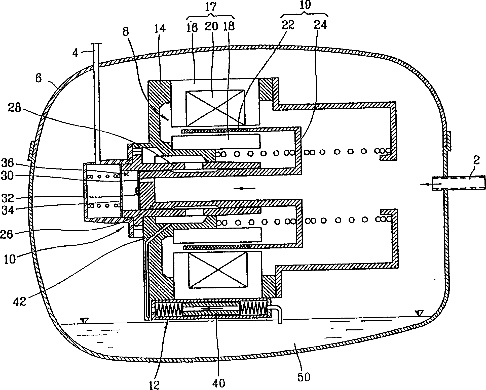
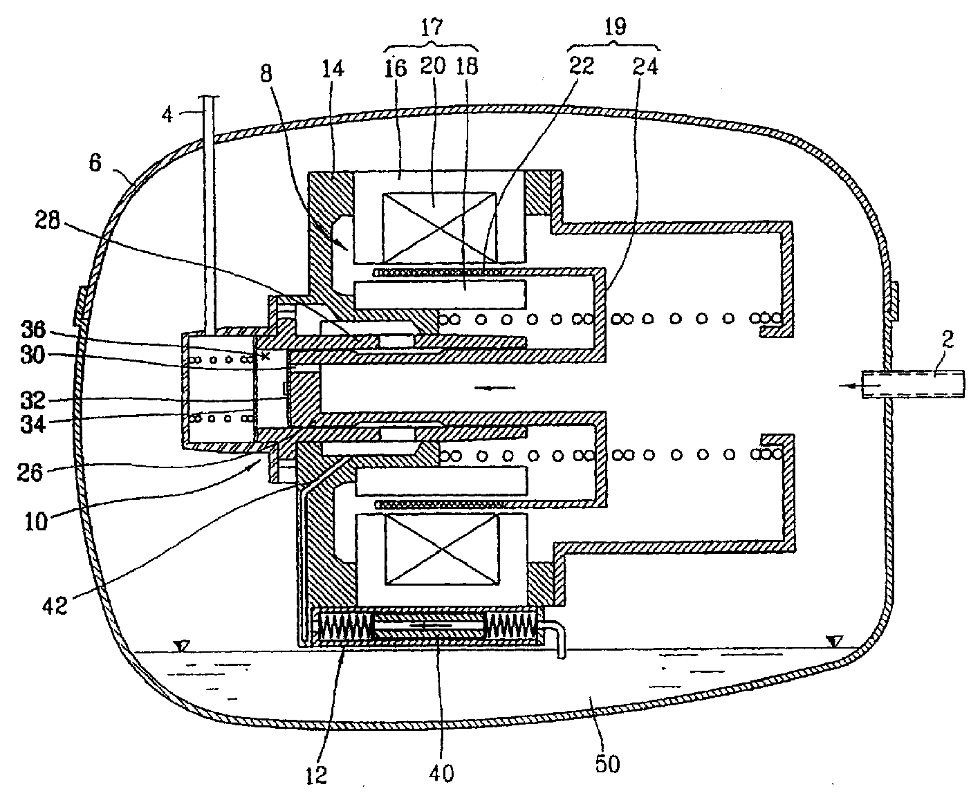
[0027] figure 1 is a cross-sectional view of a conventional reciprocating compressor used to compress refrigerant.

[0028] Such as figure 1 As shown, a conventional reciprocating compressor includes: a sealed shell 6, a suction pipe 2 for sucking in refrigerant and a discharge pipe 4 for discharging compressed refrigerant connected to it, and a reciprocating force generated inside the casing 6 The driving unit 8, the compression unit 10 for bearing the reciprocating force generated by the driving unit 8 and performing the compression operation on the refrigerant; the lubrication unit 12 for performing the lubrication operation on the moving parts of the driving unit 8 and the compression unit 10 .

[0029] The drive unit 8 includes: a cylindrical outer stator 16 fixed by a bracket 14 fixed in the sealed casing; an inner stator 18 arranged to have an air gap with the inner peripheral surface of the outer stator 16; a winding coil 20 wound around the outer stator 16, Electri...


PUM


Abstract

A reciprocating compressor comprising a drive unit (10) disposed within a sealed housing (86) and generating a reciprocating force; for performing compression on a refrigerant when subjected to a reciprocating force generated by the drive unit (8) a compression unit (10) for operation; and a lubrication unit (12) for supplying lubricant to the drive unit (8) and the compression unit (10) to complete the lubrication operation. Hydrocarbons consisting of carbon and hydrogen, a natural refrigerant, are used as refrigerants. The lubricant is a paraffin-based mineral lubricant, which is a mineral oil and harmonizes well with the natural refrigerants used in refrigerators. Therefore, the lubricating performance is improved and thus the performance of the reciprocating compressor can be enhanced.

Description

technical field [0001] The present invention relates to a reciprocating compressor for compressing a refrigerant in a refrigerator, and more particularly, to a reciprocating compressor for compressing a refrigerant which can be used for The refrigerant of the refrigerator has a good compatibility lubricant to improve the lubricity and improve the performance of the refrigerator. Background technique [0002] Since chlorofluorocarbons (CFCs) as refrigerants used in refrigerators, air conditioners, or the like are recognized as source substances for depleting the ozone layer of the stratosphere, research on refrigerant substitutes is currently being actively conducted. [0003] CFC includes R11 (trichloromonogluoromethane), R12 (dichlorodifluoromethane), R13, etc. Among them, R12, which is mainly used as a refrigerant for refrigerators, is a source material that leads to the reduction of the ozone layer and the greenhouse effect , is a material subject to regulatory restricti...

Claims


Application Information

Patent Timeline
Patent Type & Authority Applications(China)
IPC IPC(8): F04B35/04F04B39/02
CPCF04B35/045F04B39/0215F04B39/0276F04B39/0292F04B39/02
Inventor 权起峰郑圆贤李守源李东远
Owner LG ELECTRONICS INC
Learn More