Processing method of ceramic dividing disc and its device

A processing device and processing method technology, applied in the direction of ceramic molding machines, sorting, manufacturing tools, etc., can solve the problems of high manufacturing costs, achieve the effects of ensuring processing accuracy, ensuring concentricity, and reducing manufacturing costs

Inactive Publication Date: 2006-01-11
汤奋强
View PDF0 Cites 1 Cited by
  • Summary
  • Abstract
  • Description
  • Claims
  • Application Information

AI Technical Summary

Problems solved by technology

Because the concentricity of the shaft hole and the outer circle of the ceramic indexing plate, the parallelism of the planes on both sides, and the uniformity of the tooth groove are relatively high, generally large-scale equipment is used for processing, so the manufacturing cost is relatively high, and it is not yet possible in China. Finish

Method used


Image

  • Processing method of ceramic dividing disc and its device
  • Processing method of ceramic dividing disc and its device
  • Processing method of ceramic dividing disc and its device

Examples


Embodiment

[0024] Embodiment: a kind of processing method of ceramic index plate, comprises the following steps:

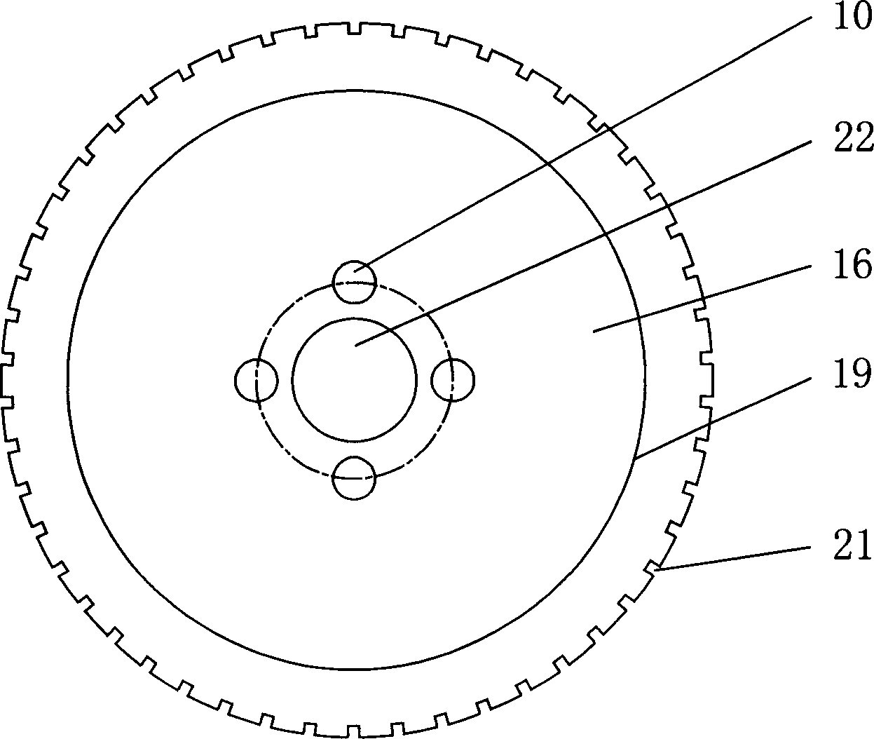
[0025] A. The ceramic indexing plate blank 6 with a certain outer circle, shaft hole 22 and thickness is processed by injection method;

[0026] B. Use a drilling machine to process the installation hole 10 around the shaft hole 22 to the required size of the part;

[0027] C. Roughly grind the planes on both sides of the blank 6 on a surface grinder;

[0028] D. Taking the installation hole 10 as the positioning reference, process the shaft hole 22 to the required size of the part;

[0029] E. Finely grind the thickness to the required size of the part on a surface grinder;

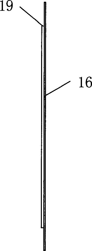
[0030] F. Clamp the blank 6 on the special tooling to roughly grind the outer circle, then grind the step 19 to the required size of the part, and then finely grind the outer circle to the required size of the part;

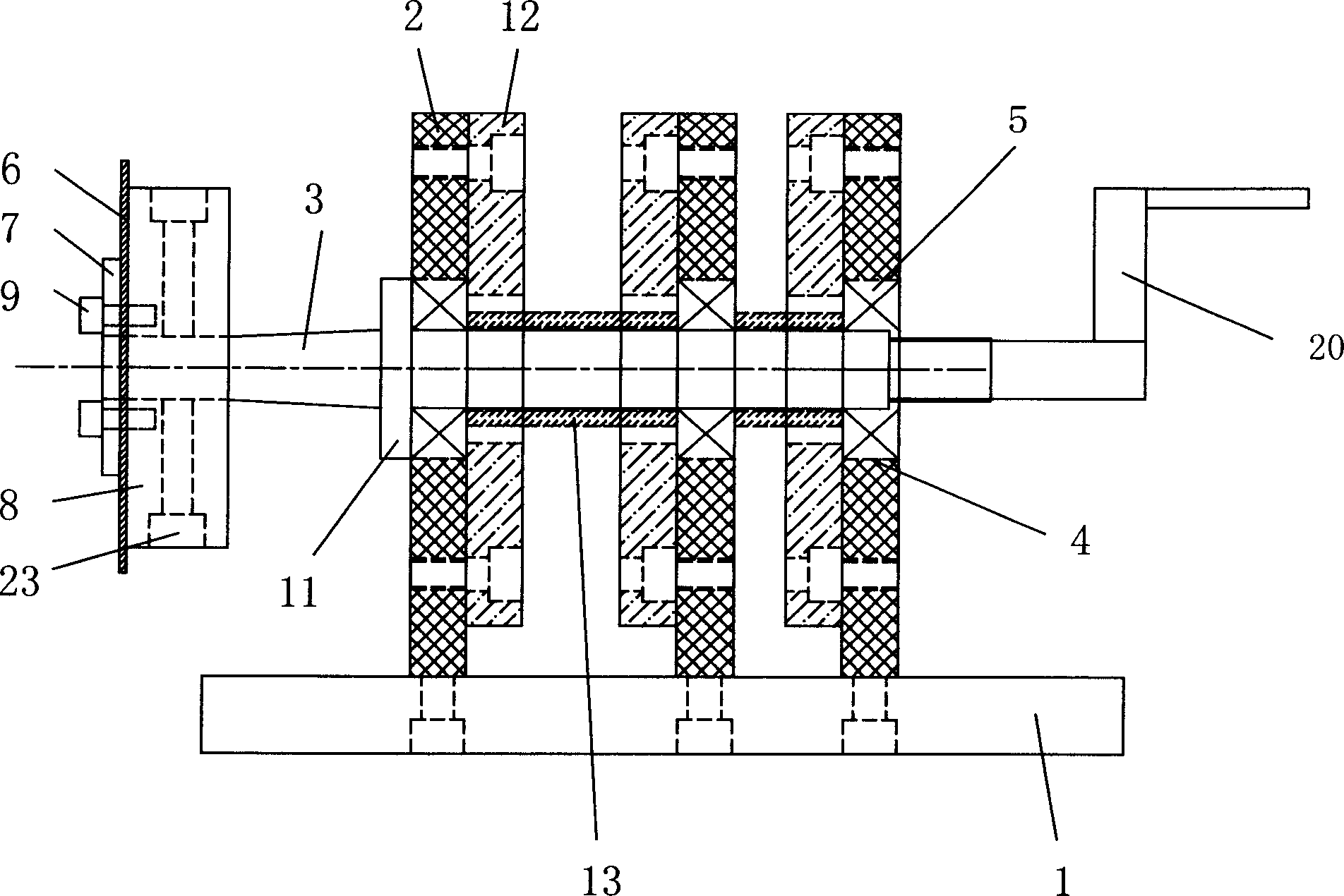
[0031] G. Equivalent wheel 14, positioning pin 17, fixed arm 18 are installed at t...


PUM


Abstract

A technology for manufacturing the ceramic index head includes such steps as preparing the blank of ceramic index head by pressure injection method, drilling installation holes, rough grinding on both lateral surfaces, machining shaft hole, fine grinding for proper thickness, and fine grinding of external circle, step, tooth slot, etc. Its apparatus is also disclosed.

Description

technical field [0001] The invention relates to a processing method and device for a ceramic indexing plate. Background technique [0002] With the rapid development of the electronics industry and the information industry, the demand for SMD electronic components is also growing rapidly. In the detection and packaging process of chip resistors and chip capacitors, it is necessary to use a ceramic indexing plate to sort the delivered components one by one. The structure of the ceramic indexing plate is as follows: figure 1 , figure 2 As shown, there is a shaft hole in the center of the indexing plate, and there are four mounting holes around the axis hole. There is a step on the edge of the indexing plate and a tooth groove on the periphery. Driven to rotate, the SMD components delivered from the front are inserted into the tooth grooves one by one, and the SMD components are sorted out after turning a certain angle under the drive of the tooth grooves, for testing or pac...

Claims


Application Information

Patent Timeline
Patent Type & Authority Applications(China)
IPC IPC(8): B28B11/00B07C5/00B28B1/00
Inventor 汤奋强
Owner 汤奋强
Why Eureka
Try Eureka