

Needleless hypodermic injection device with non-electric ignition means
A technology of hypodermic injection and ignition device, applied in the field of instruments, can solve problems such as waste, electronic ignition needleless injection instruments are not a solution, and achieve the effect of reducing manufacturing costs
- Summary
- Abstract
- Description
- Claims
- Application Information
AI Technical Summary
Problems solved by technology
Method used
Image

Examples
Embodiment 1
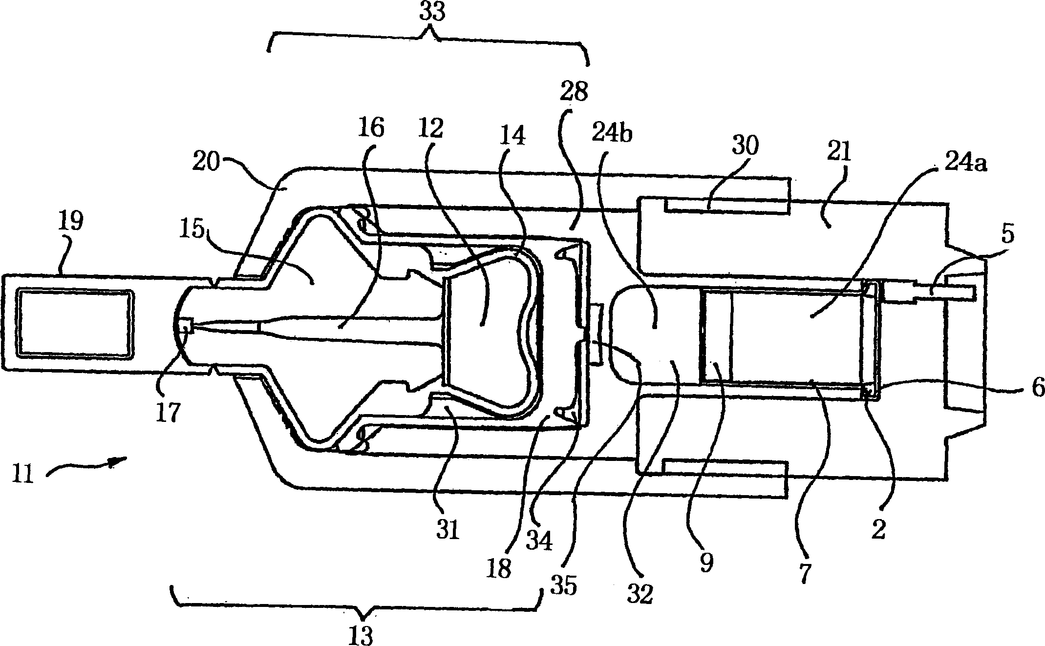
[0277] figure 1 A first embodiment of an instrument 11 according to the invention is shown. The device 11 is a cartridge characterized in that the ignition means contained therein comprise an impact-sensitive initiating material 2 and a firing pin 5 for impacting the initiating material 2 . The priming material 2 is positioned relative to the propellant 24a placed in the housing 7 such that when the firing pin 5 strikes the priming material 2, the hot products of combustion of the priming material 2 ignite the propellant 24a contained in the housing 7 and may also ignite the Additional propellant 24b within the device.
[0278] The casing 7 and the primer 2 are part of a gas generator which is part of the device 11 . The housing 7 seals off the rear of the gas generator and requires no further gas seals for this purpose.
[0279] The housing 7 is a thin brass cup with a hollow rim 6 surrounding the base. The hollow edge 6 of the casing 7 is filled with an impact-sensitive ...
Embodiment 2
[0333] Figures 17 through 24 illustrate structures suitable for use with the above figure 1 The injection device 11 is similar to the second embodiment of the ignition device that is part of the injection device.
[0334] Further examples of constructions of injection devices are described below in the description of other embodiments including different firing means. The ignition means described below with reference to Figures 17 to 24 are also applicable to those other examples of construction of the injection device.
[0335] Figure 17 shows the structure with the above figure 1 A partial view of an injection device similar to the injection device 11, but with a glass snap rod igniter 61 instead figure 1 The firing pin 5 and the impact-sensitive detonating material 2 shown in are used as the ignition device.
[0336] The igniter 61 is inserted and held in a suitable opening of an ignition plate 62 which is an airtight enclosure for the rear of the propellant chamber 63 ....
Embodiment 3
[0351] Figure 25 to Figure 3 3 shows structures suitable for use with the above figure 1 The injection device 11 is similar to the third embodiment of the ignition device that is part of the injection device. This third embodiment includes reference to Figures 25 to 3 0 describes the igniter 81 and the means for producing a mechanical impact on a point 82 of the outer surface of the igniter 81. Point 82 is located in the ignition impact region. The following will refer to Figures 31 to 3 3 describes the means for producing a mechanical impact on a point 82 of the outer surface of the igniter 81.
[0352] Further examples of constructions of injection devices are described below in the description of other embodiments including different firing means. Refer below Figure 25 to Figure 3 The ignition device described in 3 is also suitable for those other examples of the construction of the injection device.
[0353] Figure 25 shows the structure with the above figure...
PUM
| Property | Measurement | Unit |
|---|---|---|
| Diameter | aaaaa | aaaaa |
| Outer diameter | aaaaa | aaaaa |
| Free length | aaaaa | aaaaa |
Abstract
Description
Claims
Application Information