Multiple moveable wall surface drag reduction device for fluid

A drag reduction device and wall technology, applied in the directions of fluid flow, hydrodynamic characteristics/hydrostatic characteristics, hull, etc., can solve the problems of limited drag reduction effect, difficulty in promotion, and high polymer price.

Inactive Publication Date: 2006-02-08
邹立松
View PDF0 Cites 11 Cited by
  • Summary
  • Abstract
  • Description
  • Claims
  • Application Information

AI Technical Summary

Problems solved by technology

After the establishment of the boundary layer theory, after years of development, drag reduction methods can be roughly divided into four categories according to different ways to reduce viscous drag. One is the method of locally changing the fluid near the boundary, such as hovercraft technology and air lubrication technology. The resistance potential is considerable, but the specific technology and technological measures to realize the replacement of viscous fluids with very different viscosities and specific gravity at all boundaries are still difficult to completely solve, and it is difficult to promote. At present, it is mainly used in the fields of transportation and mechanical engineering
The second type is to change and control the temperature of the boundary layer, or to cha

Method used


Image

  • Multiple moveable wall surface drag reduction device for fluid
  • Multiple moveable wall surface drag reduction device for fluid
  • Multiple moveable wall surface drag reduction device for fluid

Examples


Embodiment 1

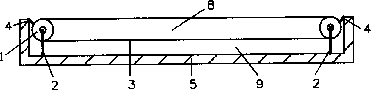
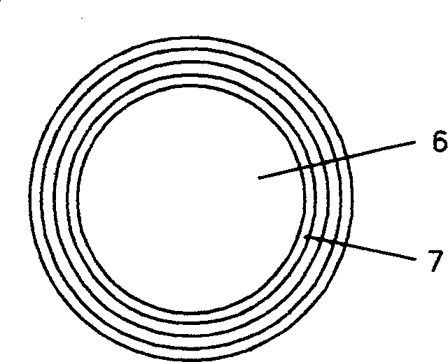
[0029] Embodiment one: Figure 6 Shown is a schematic diagram of a typical multiple movable wall fluid drag reduction device mainly used for internal flow drag reduction, in which the chamber 1 of the main movable wall system is covered with a subordinate movable wall system, and the chamber 1 of the subordinate system is located again. There is a sub-subordinate movable wall system, the brackets of which are interconnected and fixed on the shell, a subordinate movable wall system is arranged at the chamber 2 of the main movable wall system, and chamber 1 and chamber 2 of the subordinate system are respectively set There is a sub-subordinate movable wall system, each movable wall system is composed of movable wall, rotating drum and bracket, each space in the whole device is filled with lubricating fluid, and the movable wall is laminated by multiple single-layer movable walls, the specific weight The number depends on need. The filling fluid can also be determined according ...

Embodiment 2

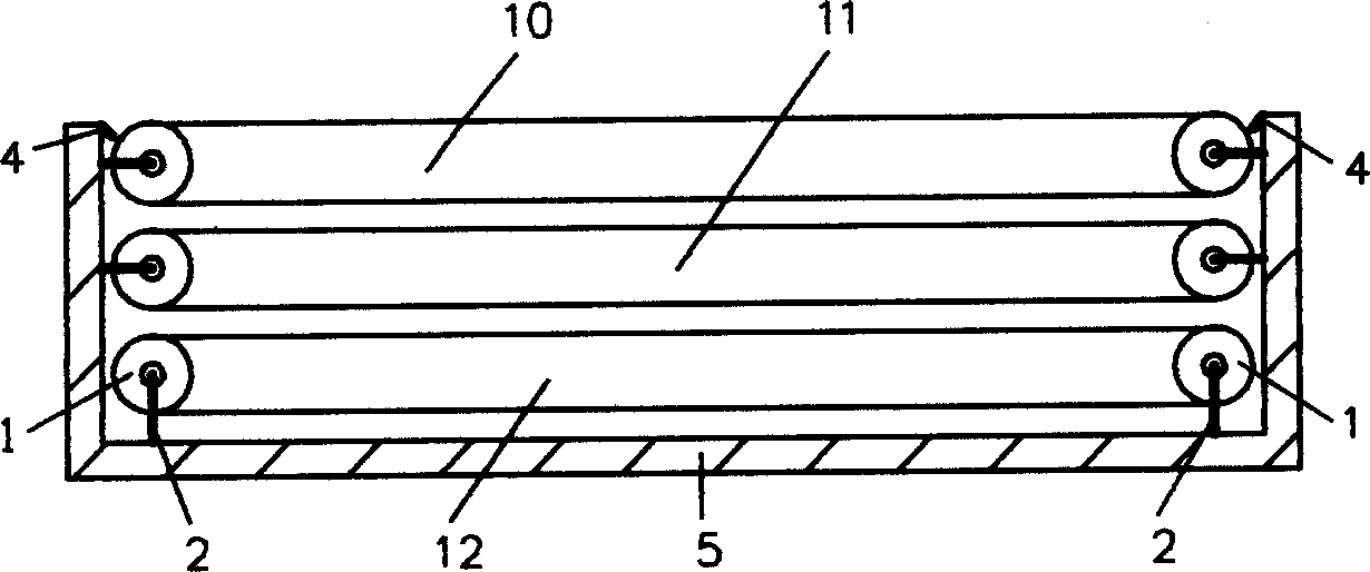
[0030] Embodiment two: Figure 7 Shown is a typical installation schematic diagram of a multiple movable wall fluid drag reduction device mainly used for outflow drag reduction. The combination method is that two main movable wall systems are juxtaposed, and the four drums of one of the main movable wall systems are installed with the bracket. On the four vertices of the drag-reducing object, the main movable wall will be surrounded by the drag-reducing object, while another main movable wall system is installed on one side. From the figure, we can see the return of the movable wall of the two main movable wall systems The sides are adjacent, because their motion directions are consistent and their speeds are roughly equal, so all the subordinate movable wall systems of the two main movable wall systems at the position of the chamber 2 can be saved. The installation method of this embodiment is especially suitable for drag reduction of slender objects moving in fluids, such as...


PUM


Abstract

One kind of fluid friction force reducer is arranged between fluid to be resistance reduced and object surface. It consists of turntable, bearing, rack, movable walls and subsidiary parts. The movable walls around the turntable move with the turntable and have their parts contacting fluid moving with the fluid to reduce resistance to the fluid. Each of the movable walls consists of several layers of wall, and the wall layers can slide freely in fixed direction. Between different wall layers, lubricating fluid is filled, and the internal fluid and external fluid are maintained in balanced pressure. There may be subsidiary movable walls inside the device. The present invention may be used in different fluid resistance reducing fields.

Description

technical field [0001] The invention relates to a drag reducing device for reducing fluid frictional resistance. Background technique [0002] For a long time, when people have been looking for ways to reduce fluid resistance, their attention has only been focused on and limited to the shape of the body, that is, to explore the streamlined aspect of the object. The current air resistance reduction design of high-speed trains, missiles, and automobiles is still at this stage. After the establishment of the boundary layer theory, after years of development, drag reduction methods can be roughly divided into four categories according to different ways to reduce viscous drag. One is the method of locally changing the fluid near the boundary, such as hovercraft technology and air lubrication technology. The resistance potential is considerable, but the specific technology and technological measures to realize the replacement of viscous fluids with very different viscosities and s...

Claims


Application Information

Patent Timeline
IPC IPC(8): F15D1/00
CPCF15D1/12Y02T70/121B63B1/36Y02T70/10
Inventor 邹立松
Owner 邹立松
Why Eureka
Try Eureka