Position detector for double grating displacement transducer metering mode and detection method thereof
A technology of displacement sensor and grating displacement, which is applied in the direction of measuring devices, optical devices, instruments, etc., and can solve problems such as limit detection speed and resolution constraints
- Summary
- Abstract
- Description
- Claims
- Application Information
AI Technical Summary
Problems solved by technology
Method used
Image
Examples
specific Embodiment approach 1
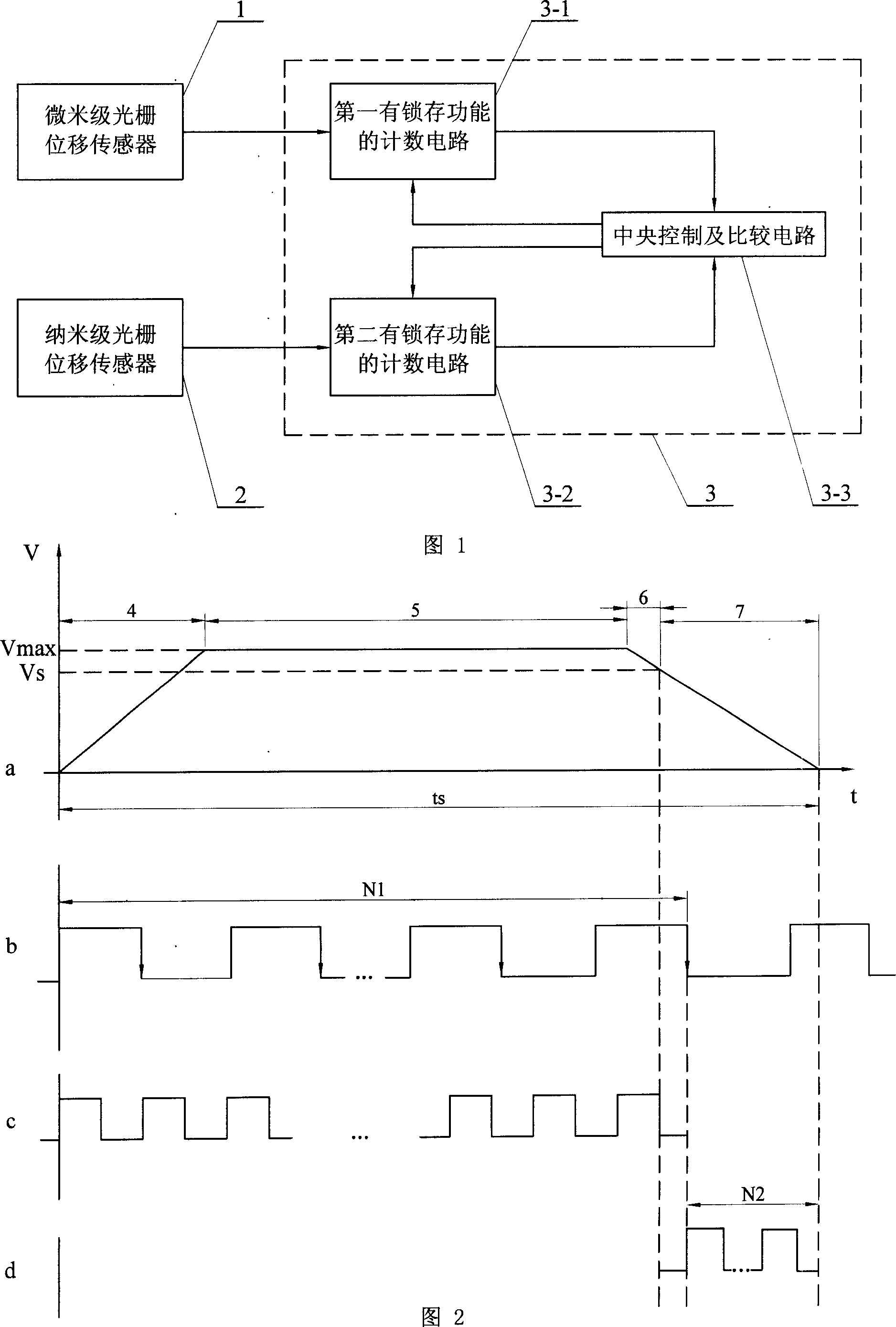
[0007] Embodiment 1: This embodiment is described in conjunction with FIG. 1. The detection device of this embodiment is composed of a micron-scale grating displacement sensor 1, a nano-scale grating displacement sensor 2, and a counting and switching circuit 3. The micron-scale grating displacement sensor 1 The signal output end is connected to the coarse grating signal input end of the counting and switching circuit 3 , and the signal output end of the nanoscale grating displacement sensor 2 is connected to the fine grating signal input end of the counting and switching circuit 3 . In this specific embodiment, the micron-scale grating displacement sensor 1 adopts a grating displacement sensor with a micron-scale resolution, and the nano-scale grating displacement sensor 2 adopts a grating displacement sensor with a nanoscale resolution.
specific Embodiment approach 2
[0008] Specific embodiment two: illustrate this specific embodiment in conjunction with Fig. 1, the difference between this specific embodiment and specific embodiment one is: its counting and switching circuit 3 are by the counting circuit 3-1 that the first latch function is arranged, the first 2. A counting circuit 3-2 with a latch function and a central control and comparison circuit 3-3. The signal output end of the micron-scale grating displacement sensor 1 is connected to the signal input end of the first counting circuit 3-1 with a latch function. The data output end of the first counting circuit 3-1 with latch function is connected to the coarse raster data input end of the central control and comparison circuit 3-3, and the control signal input end of the first count circuit 3-1 with latch function is connected The coarse grating control signal output end of the central control and comparison circuit 3-3, the signal output end of the nanoscale grating displacement sen...
specific Embodiment approach 3
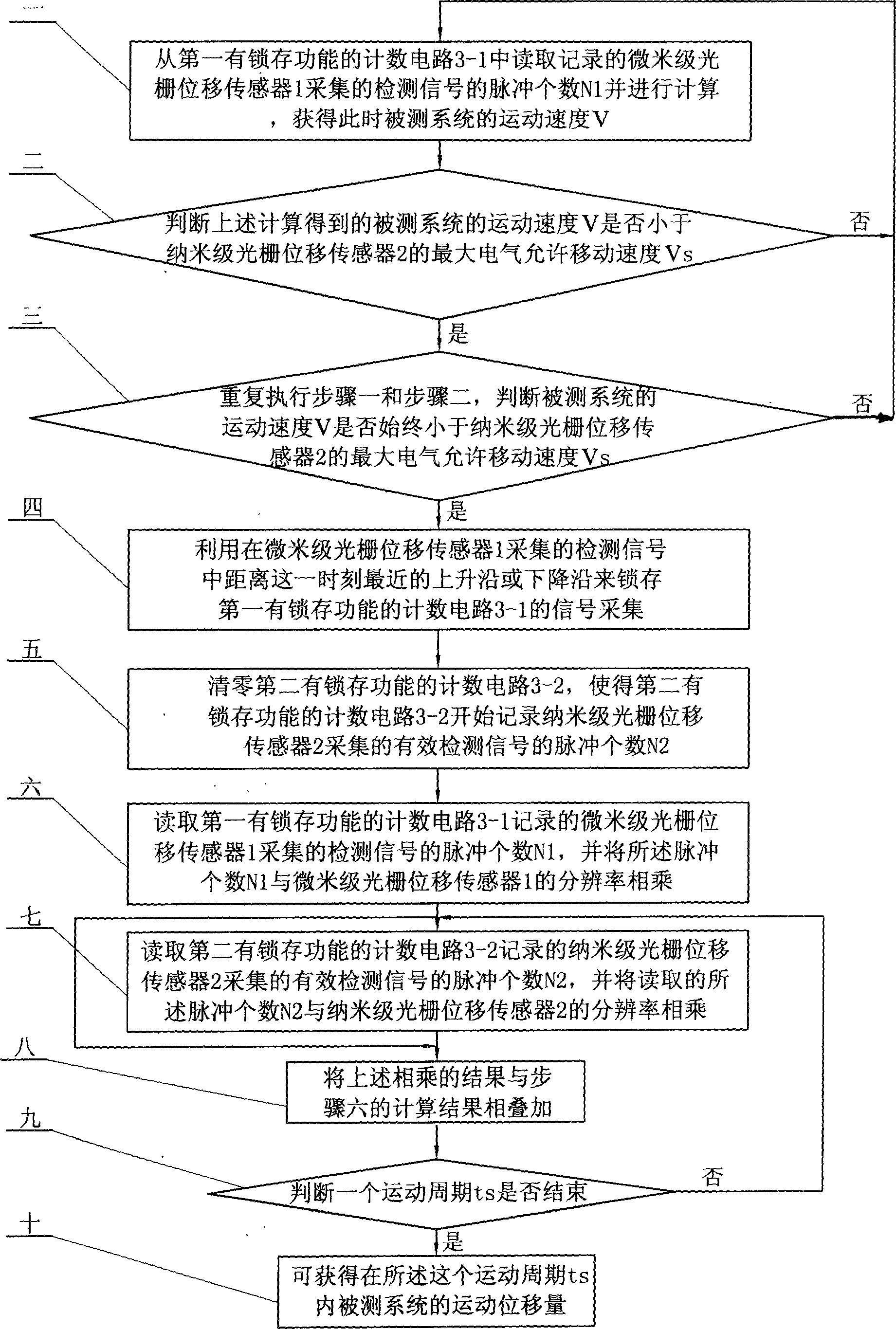
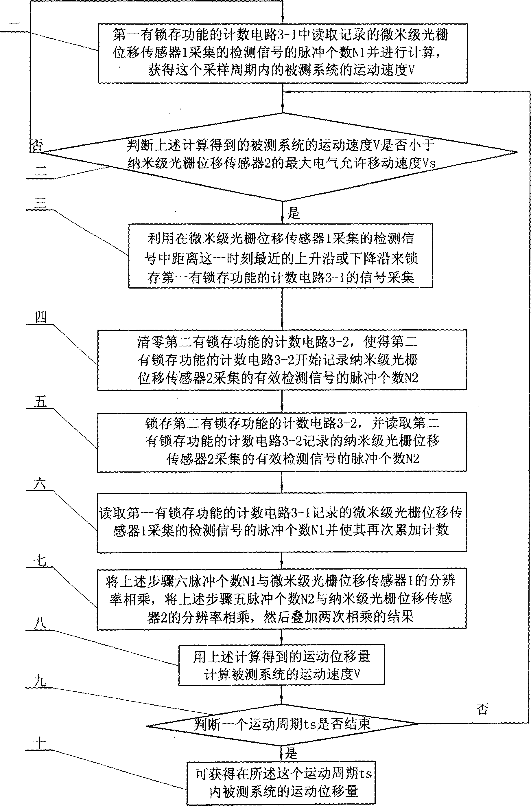
[0010] Specific embodiment three: this specific embodiment is described in conjunction with Fig. 1 and Fig. 2, the step of the detection method of this specific embodiment is: the first step: in a movement period ts of the system under test, the motion velocity of the system under test is at The acceleration process period 4, the constant speed process period 5 and the system movement speed V are greater than the maximum electrical allowable movement speed V of the nanoscale grating displacement sensor 2 s During period 6 of the deceleration process, the micron-scale grating displacement sensor 1 is always used to detect the displacement change of the system under test; the second step: when the system under test is at a system motion speed V less than the maximum electrical allowable moving speed of the nano-scale grating displacement sensor 2 V s During period 7 of the deceleration process, the nanoscale grating displacement sensor 2 is used to detect the displacement change...
PUM
 Abstract
Description
Claims
Application Information
 - R&D
- Intellectual Property
- Life Sciences
- Materials
- Tech Scout
- Unparalleled Data Quality
- Higher Quality Content
- 60% Fewer Hallucinations
Browse by: Latest US Patents, China's latest patents, Technical Efficacy Thesaurus, Application Domain, Technology Topic, Popular Technical Reports.
© 2025 PatSnap. All rights reserved.Legal|Privacy policy|Modern Slavery Act Transparency Statement|Sitemap|About US| Contact US: help@patsnap.com


