
Plasma display panel with coplanar electrodes having inclined discharge edges

A technology of plasma and coplanar electrodes, applied in the direction of AC plasma display panels, gas discharge electrodes, discharge tubes, etc., can solve the limitation of addressing speed and continuous frequency, increase the volume of pseudo-anode plasma region, and improve the luminous efficiency of plasma displays Low-level problems, to achieve the effect of limiting wear and prolonging life

Inactive Publication Date: 2006-02-22
THOMSON LICENSING SA
View PDF3 Cites 0 Cited by
  • Summary
  • Abstract
  • Description
  • Claims
  • Application Information

AI Technical Summary

Problems solved by technology

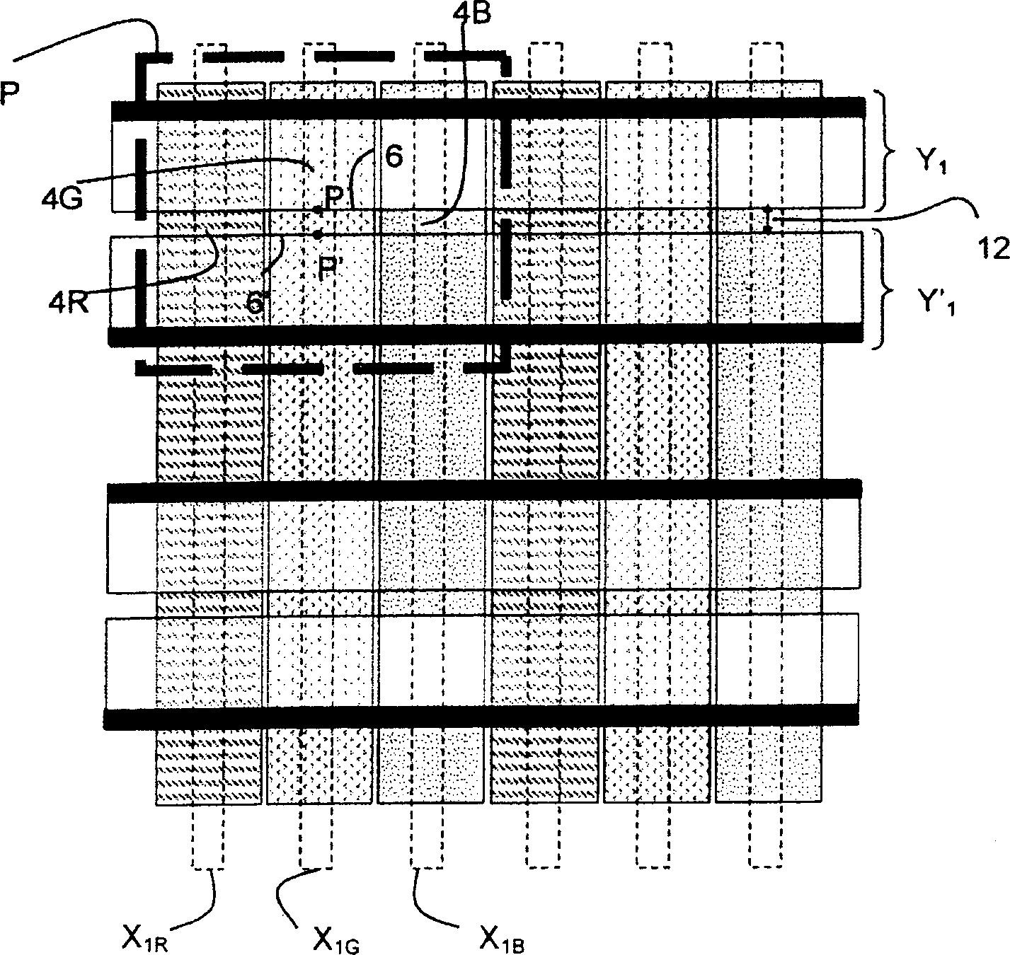
[0028] In the sustaining phase, a discharge is triggered in the cell activated at the opposite side 6, 6' of the electrode Y1, Y'1, then extends over the dielectric layer 7 between these two sides, and then on either side side expansion; this expansion occurs from the edge spanning the entire width of the electrode; this expansion makes it possible to increase the volume of the pseudo-anode plasma region, which is the discharge region considered to have high luminous efficiency; thus , this extension can increase the luminous efficiency and can obtain a uniform distribution of the UV radiation flux on the phosphor layer; however, despite this extension, the luminous efficiency of plasma displays is still relatively low
[0029] Furthermore, in the development of plasma displays, the trend to increase the resolution of the displayed image has led to a greater density of cells and therefore a smaller cell size; smaller cell size means a discharge edge in each cell6 , The length of 6' is shorter, and this limits the area exchanged between two adjacent electrodes Y1, Y'1 when the discharge is triggered, and as a result, the addressing speed and sustaining frequency are limited
[0030] The smaller size of the cells also means that the opposing separator ribs of the cells are limited to a closer approach; however, the proximity of the separator ribs causes the discharge to trigger at a given fixed point on the edges 6, 6' of the electrodes Y1, Y'1 More precise localization at P, P'; this is because the discharge has a tendency to avoid approaching the ribs, since if the onset of ionization and the discharge occurs in the vicinity of the ribs, the ionized species at the surface of the ribs The loss will extinguish the discharge; therefore, in each cell, near each separator rib, there exists a b A region where it is almost impossible to generate a discharge; the width of this region d b Typically between 20 and 60 μm; it depends on the depth of the cell (or the gap between the plates), the frequency of the voltage pulses and also on other parameters; once the separation is less than or equal to 2d from the separator rib b , then the triggering of the discharge is more and more positioned at a fixed point on the triggering side, resulting in rapid degradation of the MgO-based protective layer 8 at this point, requiring an increase in the voltage that causes the discharge at another point on the triggering side, and limiting the Display life

Method used


Image

  • Plasma display panel with coplanar electrodes having inclined discharge edges
  • Plasma display panel with coplanar electrodes having inclined discharge edges
  • Plasma display panel with coplanar electrodes having inclined discharge edges

Examples


Embodiment Construction

[0076] In order to simplify the description and illustrate the differences and advantages offered by the present invention compared to the prior art, the same reference signs are used for elements providing the same functions.

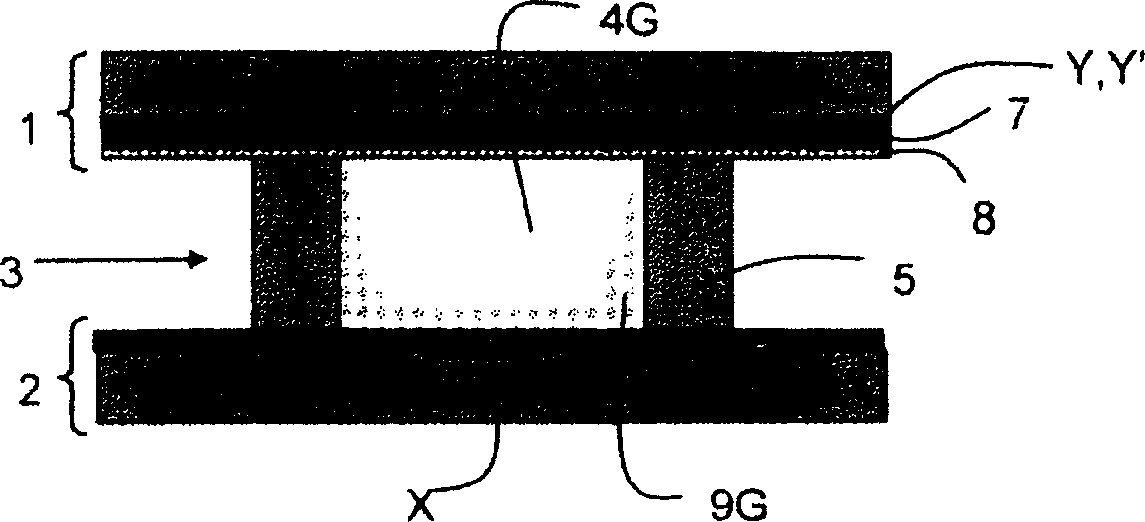
[0077] refer to Image 6 , the display according to the first embodiment of the present invention is similar to the previous reference Figure 1 to Figure 3 described display; therefore, in the remainder of the description, emphasis will be placed on differences from prior art displays; where elements are the same, reference should be made to the preceding displays; Dielectric layer of the surface electrodes; the display according to the invention comprises rectangular cells 4R, 4G, 4B arranged in a two-dimensional matrix and coplanar electrodes Y1, Y'1 across the display in a horizontal general direction.

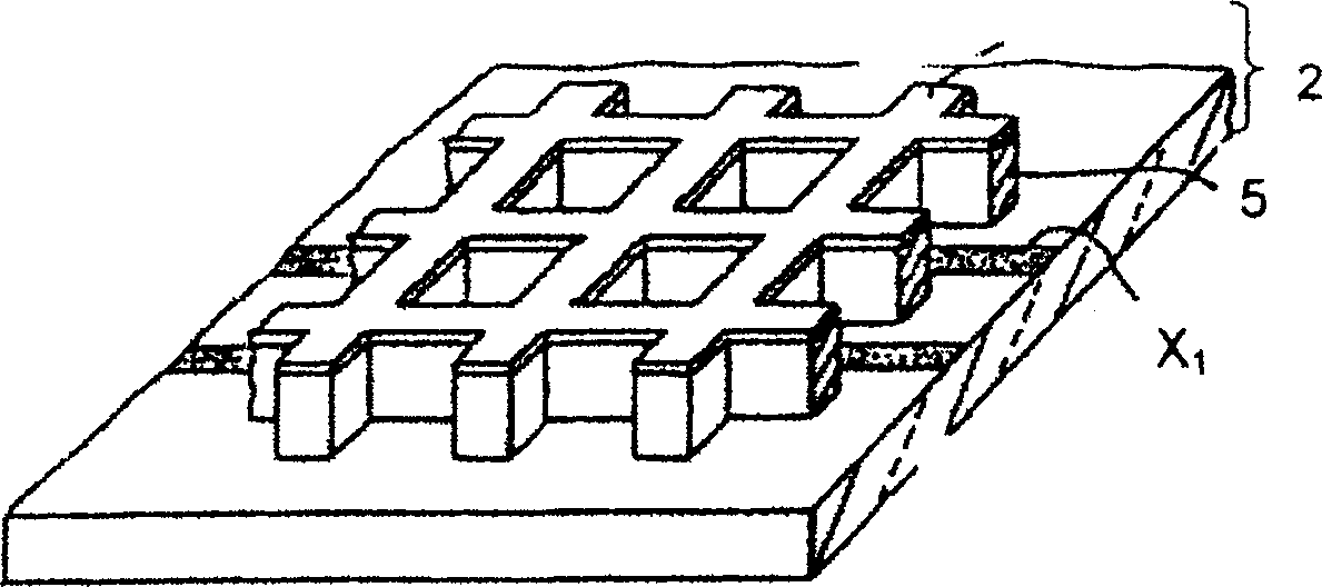
[0078] Here each cell is bounded over its entire perimeter by rectilinear separator ribs 5, 5'; the vertical separator ribs 5 limit the size of t...


PUM


Abstract

The invention concerns a panel comprising a first faceplate including at least two arrays of coplanar electrodes (Y1, Y'1) having, at each cell (4R, 4G, 4B), mutually facing edges (6, 6') separated by a constant distance (12) over a predetermined length (15) greater than the largest (14) of the dimensions of the cell in the general direction of the coplanar electrodes (Y1, Y'1); preferably, for each cell, said priming edges (6, 6') have an inclined rectilinear portion, thereby improving response time, performance and life span of the panel.

Description

technical field [0001] refer to Figure 1 to Figure 4 , the present invention relates to a plasma display, comprising: a first plate 1 and a second plate 2, between the first plate 1 and the second plate 2 is left to be filled with discharge gas and divided into discharge cells 4R, 4G, 4B The space 3 of the two-dimensional assembly, the first plate 1 has at least two so-called coplanar electrode arrays Y, Y' for triggering and providing sustaining discharges, so that said electrodes are oriented parallel to the general direction and interlaced with each other, The electrodes of each array thus traverse each cell 4, and adjacent coplanar electrodes Y1, Y'1 of different arrays have opposite sides 6, 6' at each cell 4R, 4G, 4B, opposite sides 6 , 6' are symmetrical with respect to the center point of the unit and are separated by a constant gap 12 spanning a predetermined length, which is referred to as the firing edge. Background technique [0002] A collection of cells power...

Claims


Application Information

Patent Timeline
IPC IPC(8): H01J17/04H01J17/49G09G3/291G09G3/296H01J11/12H01J11/24H01J11/32
CPCH01J2211/323H01J11/24H01J2211/245H01J11/12H01J11/32G09G3/291G09G3/296
Inventor 劳伦·泰西耶
Owner THOMSON LICENSING SA
Learn More