Piston type compressor and assembling method thereof

A compressor and piston technology, applied in the field of piston compressors, can solve problems such as deformation, harmfulness, and troublesome fixing solutions.

Inactive Publication Date: 2006-03-01
SECOP GMBH
View PDF2 Cites 7 Cited by
  • Summary
  • Abstract
  • Description
  • Claims
  • Application Information

AI Technical Summary

Problems solved by technology

But these fixed schemes are more troublesome
Heating methods, such as welding or braz

Method used


Image

  • Piston type compressor and assembling method thereof
  • Piston type compressor and assembling method thereof
  • Piston type compressor and assembling method thereof

Examples


Embodiment Construction

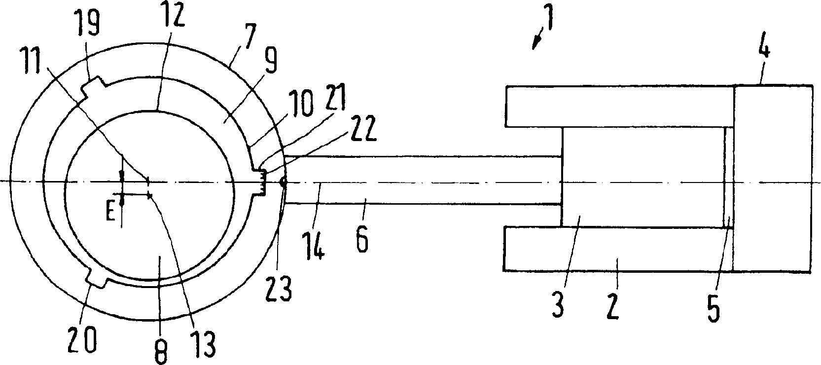
[0028] figure 1 A refrigerant compressor 1 is shown schematically and thus greatly simplified as an exemplary embodiment of a piston compressor. The refrigerant compressor 1 has a cylinder 2 in which a piston 3 can reciprocate. The cylinder 2 is closed by a cylinder head 4 . Cylinder 2, piston 3 and cylinder head 4 constitute the boundary of compression chamber 5, when piston 3 moves to the right (for figure 1 In terms of) the refrigerant gas is compressed in it as it moves.

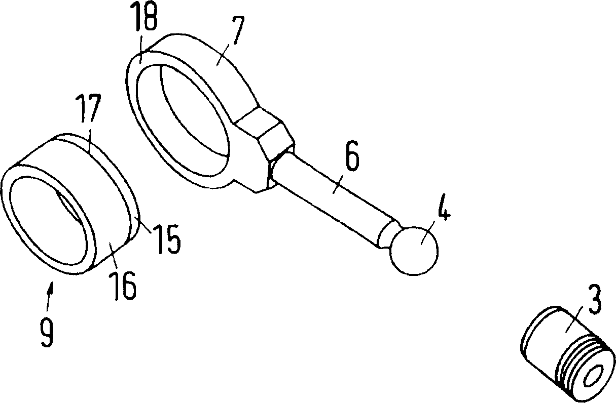
[0029] The piston 3 is driven by a connecting rod 6 whose piston-side end is hinged to the piston 3 in a manner not further shown in the figures. At its other end, the connecting rod 6 has a connecting rod bore 7 which surrounds a crank pin 8 . The figure shows that the connecting rod hole 7 is closed in the circumferential direction. But this is not strictly required.

[0030] An axle sleeve 9 is adorned between the connecting rod hole 7 and the crank pin 8 . The sleeve has an outer wall 10 of ci...


PUM


Abstract

The piston (3) is moved inside a cylinder of a refrigerant condensing device assembled of a crankshaft with a crank pin accommodated inside an eye (7) at the connecting rod (6) and a bearing bush (9) between the pin and the eye (7). The outer surface of the pin and the inner surface of the eye (7) are asymmetrically arranged. The outer surface of the bearing bush (9) is divided into a shallow sliding segment (15) and a higher main segment (16) facilitating a convenient positioning before the final pressing.

Description

technical field [0001] The invention relates to a piston compressor, in particular a refrigerant compressor, comprising a piston movable in a cylinder, a crankshaft with a crank pin, a connecting rod with a connecting rod hole surrounding the crank pin and A bushing between the crank pin and the bore of the connecting rod, the inner wall of the bushing extending eccentrically relative to its outer wall. Furthermore, the invention relates to a method for assembling such a piston compressor, in which the connecting rod bore is guided by a crank pin and the bushing is fastened between the connecting rod bore and the crank pin. Background technique [0002] The invention will be described below with reference to a refrigerant compressor as an exemplary embodiment of a piston compressor. However, the invention can also be applied to other piston compressors. [0003] Refrigerant compressors are mass-produced. One must therefore strive to keep production costs as low as possibl...

Claims


Application Information

Patent Timeline
IPC IPC(8): F04B39/14F04B49/12F16C3/22F16C3/28F16C7/06
CPCF04B39/0022F16C23/10F16C9/04F04B39/14F16C3/28F04B2201/0201
Inventor 于尔根・休斯拉斯・奥滕克里斯琴・杰普森
Owner SECOP GMBH
Why Eureka
Try Eureka