Deep-water submersible biorobot of cuttlefish imitation type mollush

A technology of bionic robots and molluscs, applied in the direction of automatic toys, non-rotating propulsion components, toys, etc., can solve the problems of complex overall structure, poor flexibility, and difficult manufacturing

Inactive Publication Date: 2006-03-08
HARBIN INST OF TECH
View PDF0 Cites 30 Cited by
  • Summary
  • Abstract
  • Description
  • Claims
  • Application Information

AI Technical Summary

Problems solved by technology

[0003] The purpose of the present invention is to solve the problems of large volume, heavy weight, poor flexibility, and great manufacturing difficulty in existing underwater robots, and the underwater bionic robot uses a motor as a power source and relies on a mechanical tr

Method used


Image

  • Deep-water submersible biorobot of cuttlefish imitation type mollush
  • Deep-water submersible biorobot of cuttlefish imitation type mollush
  • Deep-water submersible biorobot of cuttlefish imitation type mollush

Examples


specific Embodiment approach 1

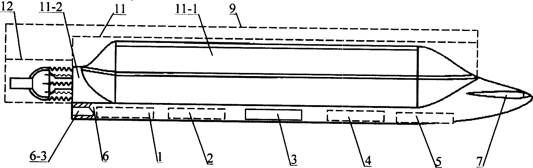
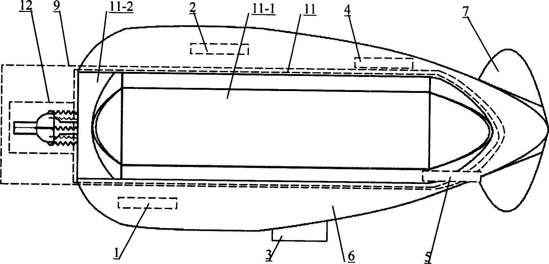
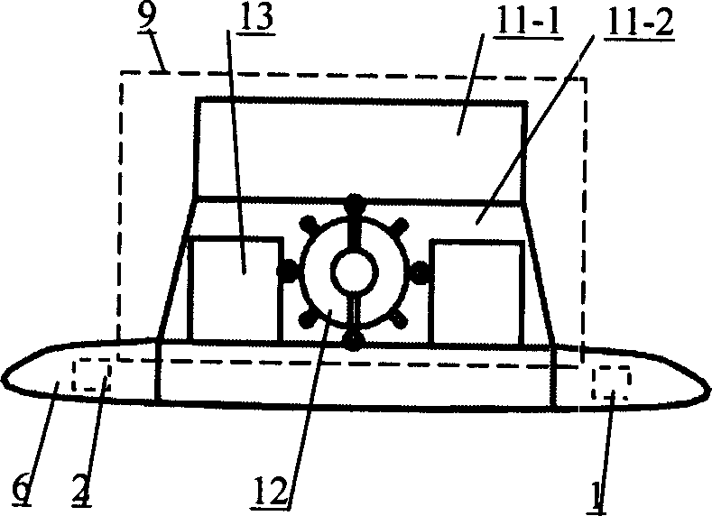
[0006] Specific implementation mode one: combine figure 1 , figure 2 , image 3 Describe this embodiment, this embodiment is made up of battery 1, control computer 2, ups and downs control device 3, motion control circuit 4, communication device 5, base body 6, monopulse thruster 9 and fin controller 7; The cavity of base body 6 6-3 are respectively fixed with a battery 1, a control computer 2, a motion control circuit 4, and a communication device 5; A fin controller 7 is fixed on the substrate 1 at the right end of the device 9 .

specific Embodiment approach 2

[0007] Specific implementation mode two: combination Figure 4 , Figure 5 , Image 6To illustrate this embodiment, the monopulse propeller 9 of this embodiment is composed of a cavity 11, a nozzle assembly 12, a cavity shape memory alloy driver 17, a cavity return spring 18, and a water inlet device; the cavity 11 is composed of a skin cavity 11-1 and the chamber 11-2; the left end of the skin chamber 11-1 is connected to the chamber 11-2 as a whole, and the skin chamber 11-1 is composed of a top plate 11-1-1, a bottom plate 11-1-2, The skin 11-1-3 is composed; the bottom plate 11-1-2 and the top plate 11-1-1 are fixedly connected through the skin 11-1-3 to form a skin cavity 11-1, and the bottom plate 11-1-2 and the base body 6 Fixed connection, a set of cavity shape memory alloy drivers 17 and a set of cavity return springs 18 are connected between the top plate 11-1-1 and the bottom plate 11-1-2, the cavity 11 is provided with a water inlet device, the cavity The left e...

specific Embodiment approach 3

[0008] Specific embodiment three: This embodiment is described in conjunction with Fig. 8, Fig. 9, and Fig. 10. The nozzle assembly 12 of this embodiment consists of a nozzle 12-1, a shape memory alloy driver 12-2 for controlling the rotation of the nozzle, and a nozzle return spring 12- 3. The nozzle pipe support 12-4, the first connection frame 12-5, the second connection frame 12-6, the third connection frame 12-7, and the fourth connection frame 12-8; the right end of the nozzle pipe support 12-4 Fixedly installed in the through hole of the left end face 11-2-3 of the chamber 11-2, the spherical surface 12-4-1 of the left end of the nozzle pipe support 12-4 is contained in the spherical cavity 12-1-1 of the nozzle 12-1 Inside and hinged with the nozzle 12-1, the spherical outer surface 12-1-2 of the nozzle 12-1 is symmetrically fixed with a group of first connecting frames 12-5 and a group of second connecting frames 12-6 along the circumferential direction, which are conne...


PUM


Abstract

The cuttlefish imitation type mollush large diving depth underwater bio-robot includes battery, control computer, sinking and floating control device, movement control circuit, communication device and base body. Besides, it also includes monopulse propeller and fin controller. Said invention also provides their connection and mounting mode.

Description

Technical field: [0001] The invention relates to an underwater bionic robot, in particular to a squid-like mollusk imitating a large diving deep underwater bionic robot. Background technique: [0002] So far, human beings have been able to conduct observation and research in outer space, but they know little about the development and utilization of deep-sea resources that are close at hand. Due to the extremely harsh environmental conditions in the deep sea, such as high pressure, no light, dark currents, complex landforms, etc., the accessibility of conventional submersibles is extremely poor, coupled with the difficulty of data transmission, the current use of marine resources by humans is still limited to shallow seas layer. Underwater robots will play a vital role in deep-sea ocean exploration and comprehensive utilization as well as in coastal defense construction. An underwater robot is another term for an underwater unmanned submersible (UUV, Unmanned Underwater Veh...

Claims


Application Information

Patent Timeline
IPC IPC(8): A63H11/18B63H1/30
Inventor 王振龙曹国辉杭观荣赵杰
Owner HARBIN INST OF TECH
Why Eureka
Try Eureka