Ultrasonic washing device
A washing device and ultrasonic technology, applied in the direction of spraying device, spraying device, liquid spraying device, etc., can solve the problems of small output, low transmission efficiency of ultrasonic vibration, and discomfort for users to use by hand.
- Summary
- Abstract
- Description
- Claims
- Application Information
AI Technical Summary
Problems solved by technology
Method used
Image
Examples
no. 1 approach
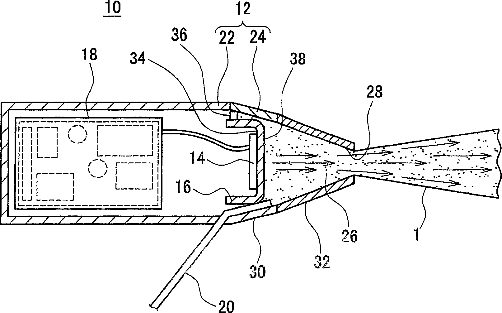
[0048] figure 1 The configuration of the ultrasonic cleaning device 10 according to the first embodiment of the present invention is shown in . The ultrasonic cleaning device 10 has a casing 12 formed of insulating synthetic resin or the like. Inside the housing 12 are provided an ultrasonic vibrator 14 , an ultrasonic transmitter 16 to which the ultrasonic vibrator 14 is bonded, a drive circuit 18 for driving the ultrasonic vibrator 14 , and the like.
[0049] The casing 12 is composed of a substantially cylindrical main body 22, a nozzle unit 24 connected to one end of the main body 22, and the like. A water supply pipe 20 is connected to the nozzle portion 24 , and a cleaning liquid is supplied to an internal cavity (cavity) 26 of the nozzle portion 24 from a cleaning liquid tank (not shown). The nozzle portion 24 has, for example, a truncated cone shape, and its cross-sectional area becomes smaller as it is formed closer to the tip of the casing 12 . In addition, the t...
no. 2 approach
[0062] under, Figure 4 The configuration of the ultrasonic cleaning device 10 according to the second embodiment of the present invention is shown in . In addition, the description of the part which is substantially the same as the said 1st embodiment and the 2nd embodiment is abbreviate|omitted, and only a different point is demonstrated.
[0063] Such as Figure 4 As shown, in the ultrasonic cleaning device 10 according to the second embodiment, the ultrasonic transmitting body 16 is substantially in the shape of a truncated cone, and at least the part protruding into the cavity 26 of the nozzle part 24 is formed closer to the nozzle-side end, that is, The cross-sectional area of the ultrasonic radiation surface 16A in a direction parallel to the joint surface with the ultrasonic vibrator 14 gradually decreases. In addition, the shape of the nozzle portion 24 is formed into a substantially truncated cone shape in which the cross-sectional area becomes narrower as it app...
no. 3 approach
[0086] Next, the configuration of the ultrasonic cleaning device 10 according to the third embodiment of the present invention will be described. In the third embodiment, the ultrasonic cleaning device 10 is a battery-type device. Note that descriptions of substantially the same parts as those in the above-described embodiments will be omitted, and only differences will be described.
[0087] exist Figure 21 In the ultrasonic cleaning device 10 shown in the figure, a rechargeable storage battery 19 and a pump 46 are arranged inside the main body 22 of the casing 12. In addition, at the rear portion of the main body 22, a washing liquid for storing the washing liquid is detachably installed. tank 48. In this way, by providing the cleaning solution tank 48 in the ultrasonic cleaning device 10 itself to form a battery-type device, it is possible to provide an ultrasonic cleaning device excellent in portability and operability.
[0088] Figure 22 A modified example having a ...
PUM
 Abstract
Description
Claims
Application Information
 - R&D
- Intellectual Property
- Life Sciences
- Materials
- Tech Scout
- Unparalleled Data Quality
- Higher Quality Content
- 60% Fewer Hallucinations
Browse by: Latest US Patents, China's latest patents, Technical Efficacy Thesaurus, Application Domain, Technology Topic, Popular Technical Reports.
© 2025 PatSnap. All rights reserved.Legal|Privacy policy|Modern Slavery Act Transparency Statement|Sitemap|About US| Contact US: help@patsnap.com


