
Method and apparatus for distortion control for optical transmitters

A transmitter and optical fiber transmission technology, applied in the field of optical transmitters, which can solve problems such as changeability and strong distortion

Inactive Publication Date: 2006-03-29
EMCORE INC
View PDF5 Cites 7 Cited by
  • Summary
  • Abstract
  • Description
  • Claims
  • Application Information

AI Technical Summary

Problems solved by technology

Although distortion is also present when the laser is linked to a fiber, it is not as strong and variable as the ECL distortion

Method used


Image

  • Method and apparatus for distortion control for optical transmitters
  • Method and apparatus for distortion control for optical transmitters
  • Method and apparatus for distortion control for optical transmitters

Examples


Embodiment Construction

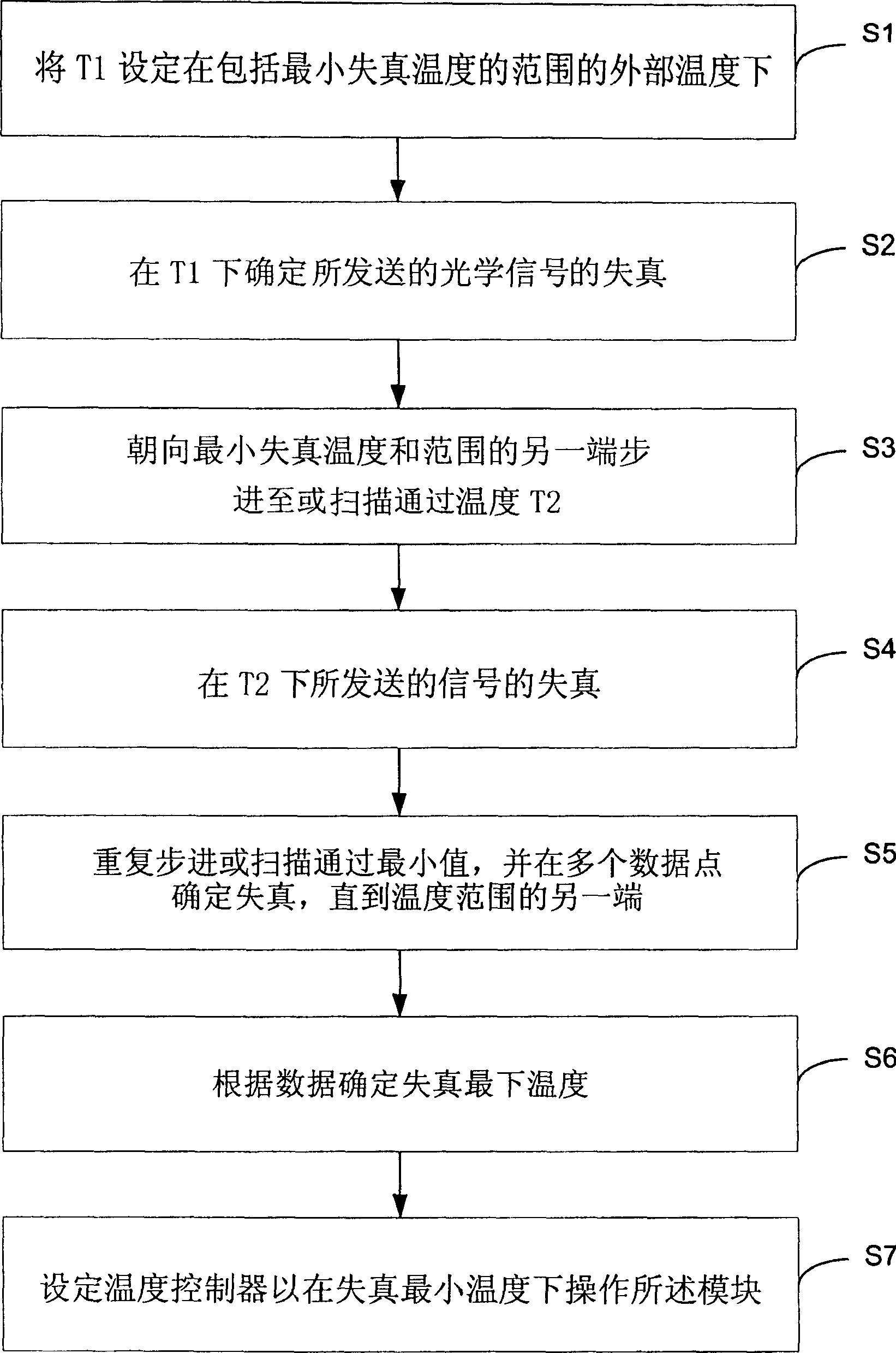
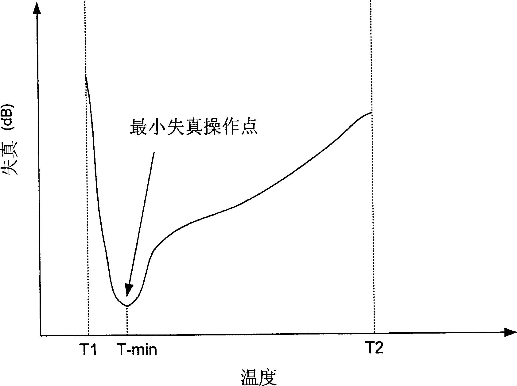
[0022] figure 1 An exemplary arrangement for determining the temperature at which a distortion minimum exists for an optical transmitter is illustrated in block form in . Module 2 is shown with an electrical terminal 4 and an optical terminal 6 . Cable 8 is coupled to module 2 at electrical end 4 , while fiber optic cable 10 is coupled to module 2 at optical end 6 . The module comprises a light source 12 emitting an optical signal based on an electrical input signal. By placing the light source in close proximity to the optical end 6 and / or by providing a light guide between the light source 12 of the module 2 and the optical end 6, the emitted optical signal is guided into the housing such as a fiber optic cable optical media. figure 2 An electro-optical converter module 14 is also schematically shown in FIG.

[0023] figure 1 The optical transmitter module 2 is also illustrated as including a temperature sensor (TS) 16 and a temperature controller (TC) 18 . The temper...


PUM


Abstract

A method of manufacturing an optical transmitter includes assembling a laser device on a module including a temperature sensor and a temperature controller. An optimum operating temperature of the laser to minimize optical distortion is determined at a temperature within a range between which distortions were determined at multiple temperatures. The temperature controller is selectively adjusted so as to operate the laser at the optimum temperature. The distortion may also be monitored during active laser operation. The temperature controller may be selectively adjusted, based on the monitoring of the distortion, so as to operate the laser at a new controlled temperature nearer that which produces the temperature-dependent distortion minimum.

Description

technical field [0001] This invention relates to optical transmitters, and in particular to fabricating an optical transmitter to minimize the temperature dependent distortion characteristics of an optical signal transmitted through an optical fiber. Background technique [0002] An alternative to modems that transmit analog or binary digital information via voltage signals on a conductor uses optical (light) signals on a fiber optic cable. Electrical signals (high / low voltage) from analog RF or digital circuits can be converted to amplitude or frequency modulated optical signals by LEDs or solid state lasers such as VCSELs or edge emitting lasers. Likewise, an optical signal can be converted back to electrical form by using a photodiode or phototransistor for introducing it into the input of an amplifier, demodulator, or other type of circuit. [0003] Laser resonators have two different types of modes: transverse and longitudinal. Transverse modes indicate that they are ...

Claims


Application Information

Patent Timeline
IPC IPC(8): H04B10/155H04B10/18G02B6/10H01S5/026H01S5/0683H04B10/07H04B10/2507
CPCH01S5/06837H04B10/0799H04B10/25H04B10/503H04B10/516
Inventor 约翰·迈克尔·扬内利
Owner EMCORE INC
Learn More