Reluctance type linear oscillating motor and its integrative application device and power supply method

A reluctance type and motor technology, applied in the direction of electromechanical devices, electrical components, etc., can solve the problems of increasing the size of the application device, the utilization of power supply voltage, and increasing the reactive power loss of the motor, so as to achieve the goal of increasing the volume and cost, and improving the utilization rate Effect

Inactive Publication Date: 2006-04-05
张玉宝
View PDF0 Cites 14 Cited by
  • Summary
  • Abstract
  • Description
  • Claims
  • Application Information

AI Technical Summary

Problems solved by technology

[0004] (1) In the process of rectification and utilization of single-phase alternating current in the prior art, only half of the waveform of the power supply voltage is used, that is, the pulsating direct current of one and a half cycles of alternating current is used to supply two excitation coils at the same time to generate the internal magnetic field force of the motor , there is insufficient utilization of the supply voltage
[0005] (2) The existing technology is a one-way output structure. During the output, the mover core is affected by the restraint and reaction force of the energy storage return spring, which increases the reactive power loss of the motor and reduces the effective output capacity of the motor.
[0006] (3) When the moving iron core type linear motor of the prior art is combined and applied as the power device of the air compressor, the moving iron core relies on the ejector rod to push the piston to perform energy conversion and output in the external cylinder, resulting in the failure of the application device. volume increased a lot

Method used


Image

  • Reluctance type linear oscillating motor and its integrative application device and power supply method
  • Reluctance type linear oscillating motor and its integrative application device and power supply method
  • Reluctance type linear oscillating motor and its integrative application device and power supply method

Examples


Embodiment Construction

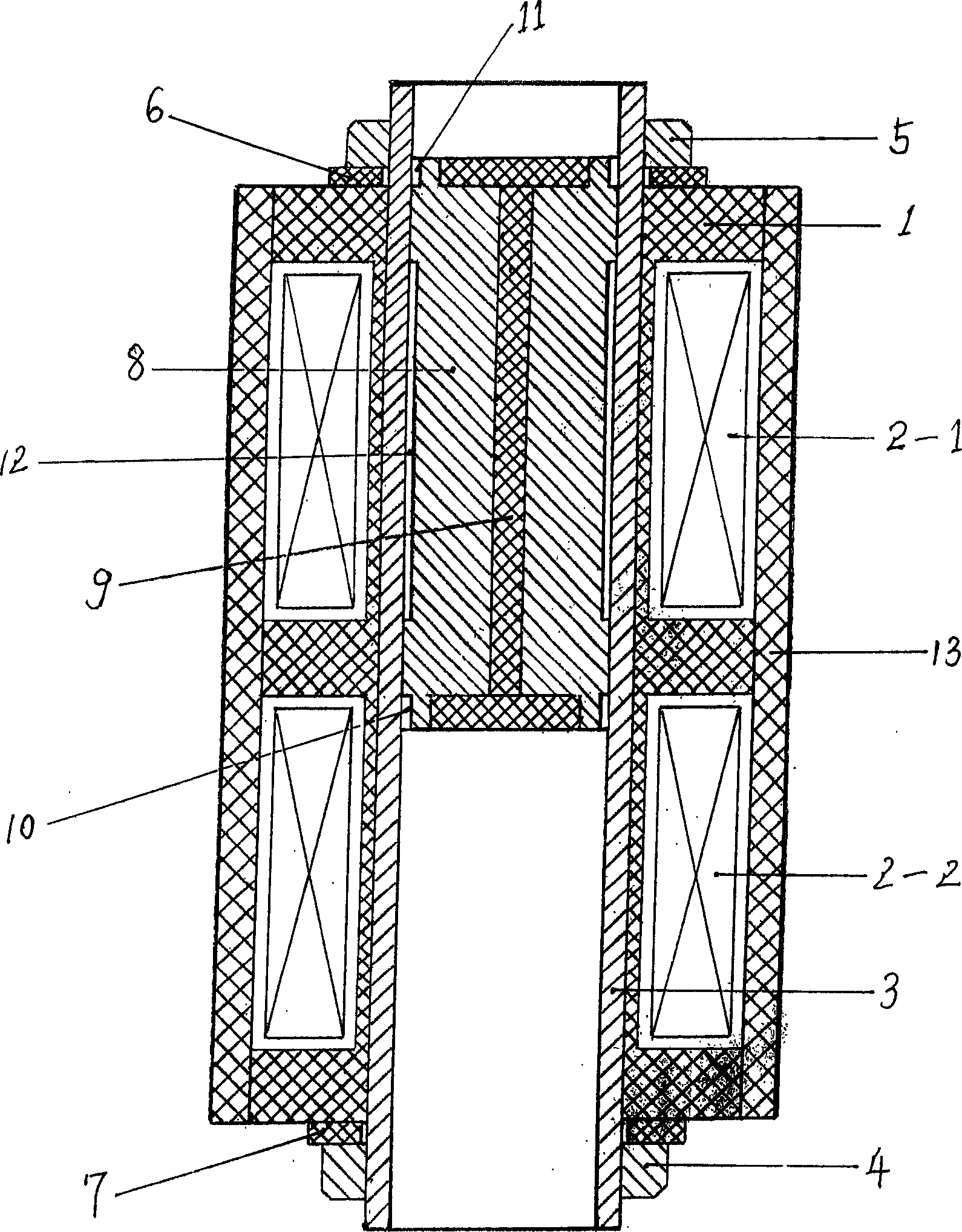
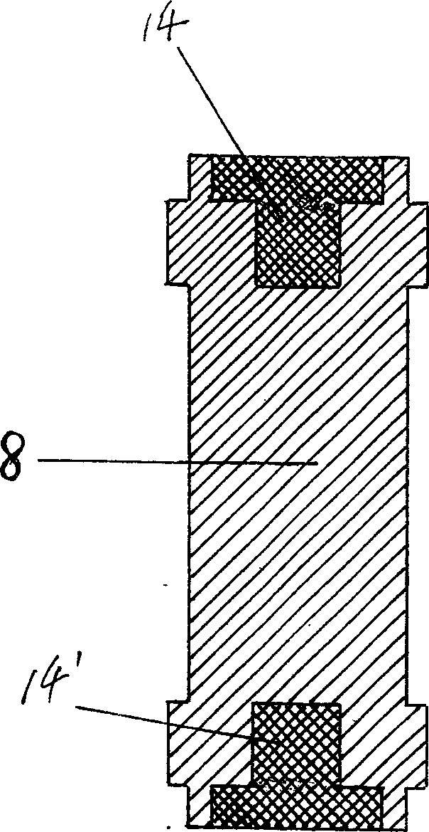
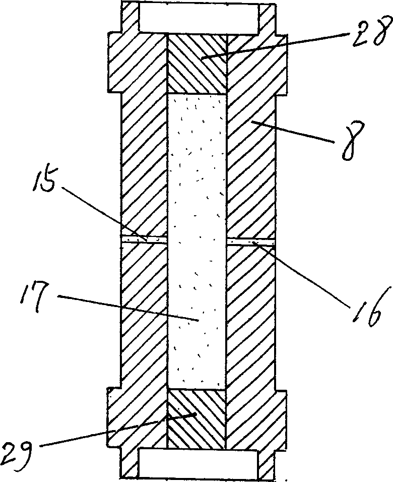
[0033] according to figure 1 As shown, the reluctance linear oscillating motor of the present invention is that two excitation coils 2-1 and 2-2 are coaxially arranged, and their skeletons are made of polyimide engineering plastics into an independent whole as a motor. Cylinder 1. A cylinder liner 3 made of ordinary brass is also installed in the cylinder body 1. After its outer circular side is processed into a threaded surface and coated with silicone grease, the brass nuts 4 and 5 at both ends and the silicone rubber gasket 6 and 7, fix it at the center of the motor, and then place a cylindrical mover core 8 with an overall size not less than the length of an excitation coil in the cylinder liner 3, the cylindrical mover core 8 is made of silicon steel, and The surface of the running-in part at both ends is hardened by chrome plating. In order to reduce the inertia of the cylindrical mover core 8 and improve its dynamic response speed, the cylindrical mover core 8 is made...


PUM


Abstract

The invention discloses a reluctance linear oscillating motor which axially assembles two excitation coils (2-1 and 2-2) and utilizes the pulsating direct current excitation of positive and passive half-periods of single-phase alternating current to be flowed in the two excitation coils (2-1 and 2-2) on the two ends of motor to make the magnetic field back and forth reposition between two ends of motor, and the iron core (8) of cylinder mover inside the motor utilizes the magneto-resistive least principle to back and forth reposition following the magnetic reluctance, and straightly repeating moves inside the cylinder with two-way output function; and it has the characters of plunger piston and cylinder of compressor to realize the continuous output of liquid or gas via the bridge rectifying tube formed by four one-way control valves on the two ends of motor. And the motor uses the silicone lubricant to make the high pressure gas output by the air compressor without oil and the two-way output structure of said reluctance linear oscillating motor can be demounted to supply linear driving motor with independent power source for impacting and compressing to simplify the structure of these machines.

Description

Technical field: [0001] The present invention relates to a linear motor, in particular to a reluctance type linear oscillating motor which uses the "minimum reluctance principle" to directly convert electric energy into linear reciprocating mechanical energy without going through any intermediate conversion mechanism. An integrated application device of a motor, a power supply method and a method for decomposing a bidirectional output structure into a unidirectional output structure. Background technique: [0002] One manufactured by Japan's Nitto Koki Co., Ltd.: "Air compressor driven by moving iron core type linear motor (AI015-0920)", which is a key component of air conditioners and refrigerators. It uses a 50Hz power supply and is powered by diode rectification. "The mover iron core that is arranged transversely to the excitation coil in the motor. "Push the piston upward during the positive half cycle, and use the spring to push back during the negative half cycle", wh...

Claims


Application Information

Patent Timeline
Patent Type & Authority Applications(China)
IPC IPC(8): H02K33/12
Inventor 张玉宝
Owner 张玉宝
Why Eureka
Try Eureka