Robot

A robot and motor technology, applied in the field of robots, can solve the problems of low limit stroke speed, shortened life of parts, and heavy weight, and achieve the effect of suppressing the increase of current consumption, avoiding large-scale and extending the stroke.

Active Publication Date: 2006-04-12
SANKYO SEIKI MFG CO LTD
View PDF1 Cites 4 Cited by
  • Summary
  • Abstract
  • Description
  • Claims
  • Application Information

AI Technical Summary

Problems solved by technology

[0005] However, in a robot configured in this way, when a large stroke in the up and down direction is required (in the Figure 5 Indicated by the symbol S), the guide 102 must be extended up and down, and the height of the fixed frame 101 must be increased accordingly
In this case, since the overall height A of the device will inevitably become larger and must be supported firmly, there is a problem that the entire robot becomes larger and heavier
[0006] In addition, when a structure in which the hand 103 is moved along one guide 102 is adopted, if the workpiece is to be moved up and down quickly, the hand 103 can only be raised and lowered at a corresponding speed. Small, and if it is made to operate at high speed, the life of parts, etc. will be shortened accordingly

Method used


Image

  • Robot
  • Robot
  • Robot

Examples


Embodiment Construction

[0029] The configuration of the present invention will be described in detail below based on the embodiments shown in the drawings.

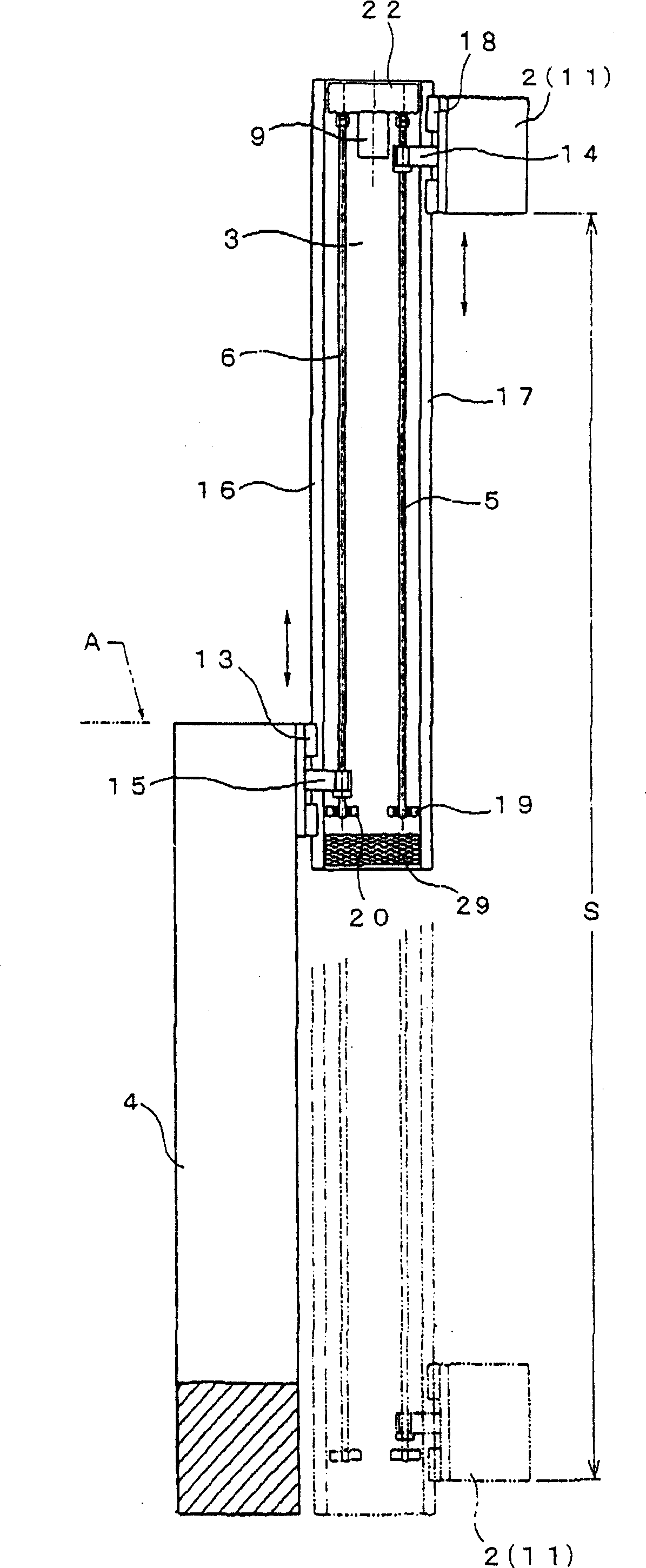
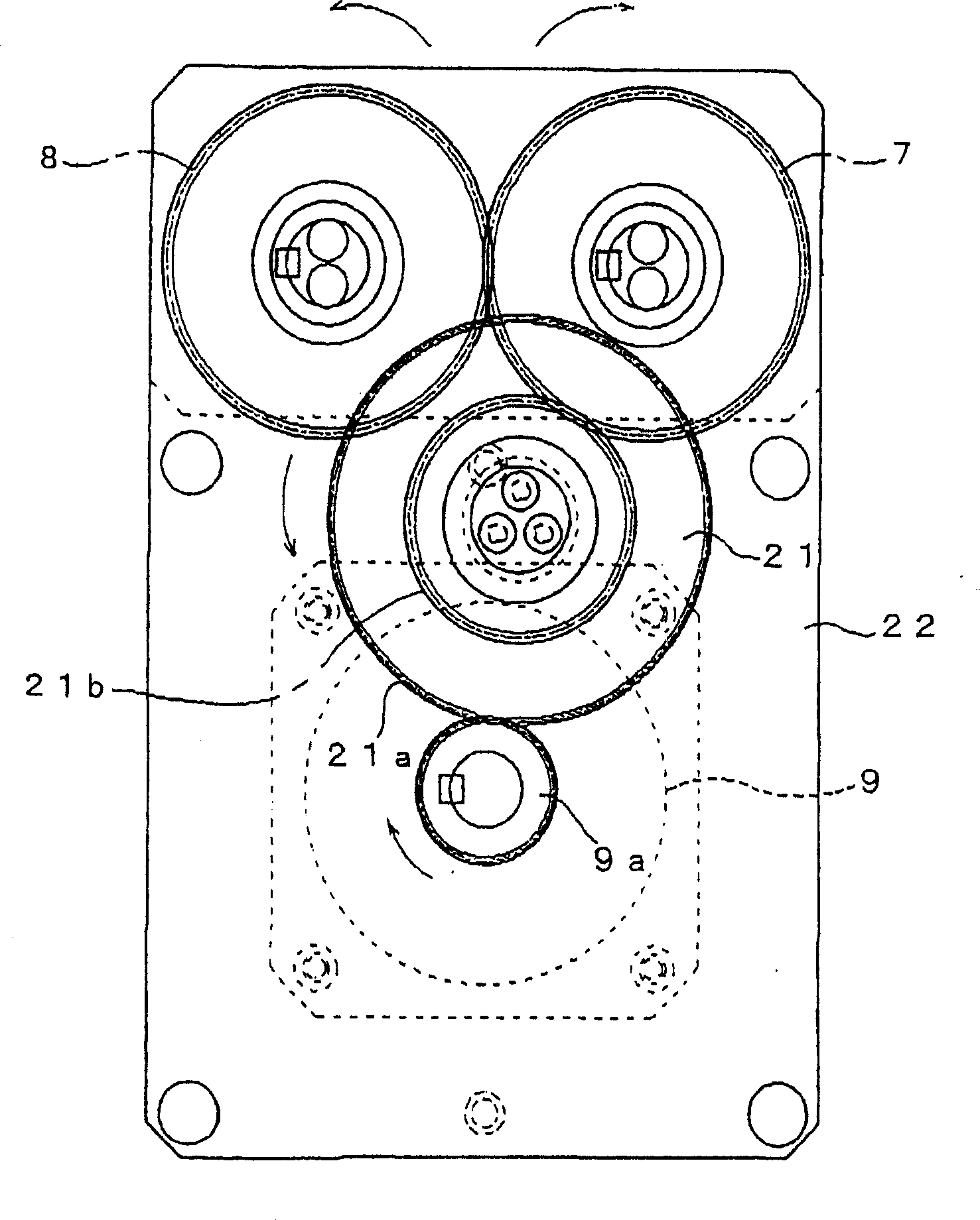
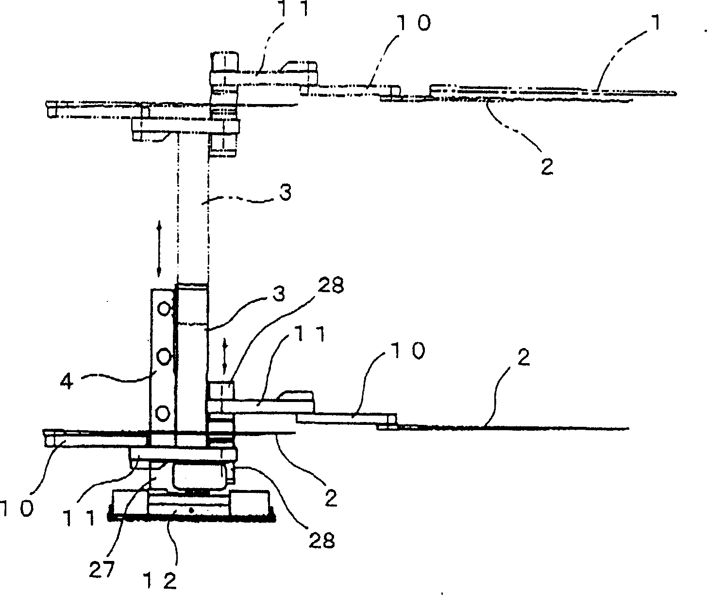
[0030] Figure 1 ~ Figure 3 An example of the present invention is shown. The robot of the present invention has the hand 2 that holds the workpiece 1, and the robot of the present embodiment includes a first frame 3 that supports the hand 2 that can move up and down and a second frame 4 that supports the first frame 3 that can move up and down. Inside the first frame 3, a first ball screw 5 for moving the hand 2 up and down and a second ball screw 6 for moving the first frame 3 up and down relative to the second frame 4 are arranged side by side in the vertical direction. The motor 9 is directly or indirectly connected to the first gear 7 that rotates integrally with the first ball screw 5 and the second gear 8 that rotates integrally with the second ball screw 6 .

[0031] More specifically, in this embodiment, the motor 9 and the gear train...


PUM


Abstract

To provide a robot which is capable of assuring a long up-and-down stroke of a hand part and increasing moving speed of the hand part while avoiding increase in size and weight of an entire device. The robot includes a first frame 3 movably supporting a hand part 2 in an upward or downward direction and a second frame 4 movably supporting the first frame 3 in an upward or downward direction. A first ball screw 5 for moving the hand part 2 up and down and a second ball screw 6 for moving the first frame 3 up and down with respect to the second frame 4 are arranged in an up-and-down direction in a parallel manner in the first frame 3. Further, the first frame 3 houses a motor 9 which is directly or indirectly connected with a first gear integrally rotating with the first ball screw 5 and a second gear integrally rotating with the second ball screw 6.

Description

(1) Technical field [0001] The present invention relates to a robot, and more particularly to an improvement in the structure of a robot having a hand for holding a workpiece. (2) Background technology [0002] A conveying robot having a hand holding a workpiece is used as a device for storing or conveying glass substrates for liquid crystal panels (these are referred to as "workpieces" in this specification) in a workpiece storage box. [0003] There is a robot in the prior art, such as Figure 5 As shown, there is a guide 102 in the up-down direction on the fixed frame 101 made of fixed pillars, so that the hand 103 moves up and down along the guide 102 (symbol A in the figure indicates the overall height of the device). As a configuration for moving the hand 103 up and down, there is a Figure 5 The difference shown is, for example, a structure in which a hand is moved by driving a pulley and a belt through a reducer with a servo motor incorporated in a fixed frame (refer...

Claims


Application Information

Patent Timeline
Patent Type & Authority Applications(China)
IPC IPC(8): B25J19/00B25J13/00B25J9/00B65G47/06
CPCB25J9/0021B25J9/02B25J15/0014
Inventor 矢泽隆之竹内靖典荒川洋
Owner SANKYO SEIKI MFG CO LTD
Why Eureka
Try Eureka