Connection branch pipe

A technology for connecting branch pipes and branch pipes, which can be used in branch pipelines, pipes, pipes/pipe joints/pipe fittings, etc.

Inactive Publication Date: 2006-04-12
ARONKASEI
View PDF2 Cites 2 Cited by
  • Summary
  • Abstract
  • Description
  • Claims
  • Application Information

AI Technical Summary

Problems solved by technology

[0010] However, in the above-mentioned conventional structure, when the second short pipe is rotated to lift up the locking part, the rubber ring is compressed and deformed to press fit to the inner diameter part or the outer surface of the peripheral part of the mounting port, or the branch pipe is connected to the outer surface of the peripheral part. When the threaded portion of the pipe and the threaded portion of the inner pipe are twisted and the inner pipe is lifted up, and then the sealing portion of the inner pipe is tightly f...

Method used


Image

  • Connection branch pipe
  • Connection branch pipe
  • Connection branch pipe

Examples


Embodiment 1

[0044] according to Figure 1 to Figure 6 The illustrated embodiments illustrate the invention in detail.

[0045] In this embodiment, the case where the connection branch pipe 1 is used to connect the installation pipe (not shown) which is the branch pipe connected to the common tank of each household to the sewage main pipe 2 which is the main pipe is exemplified.

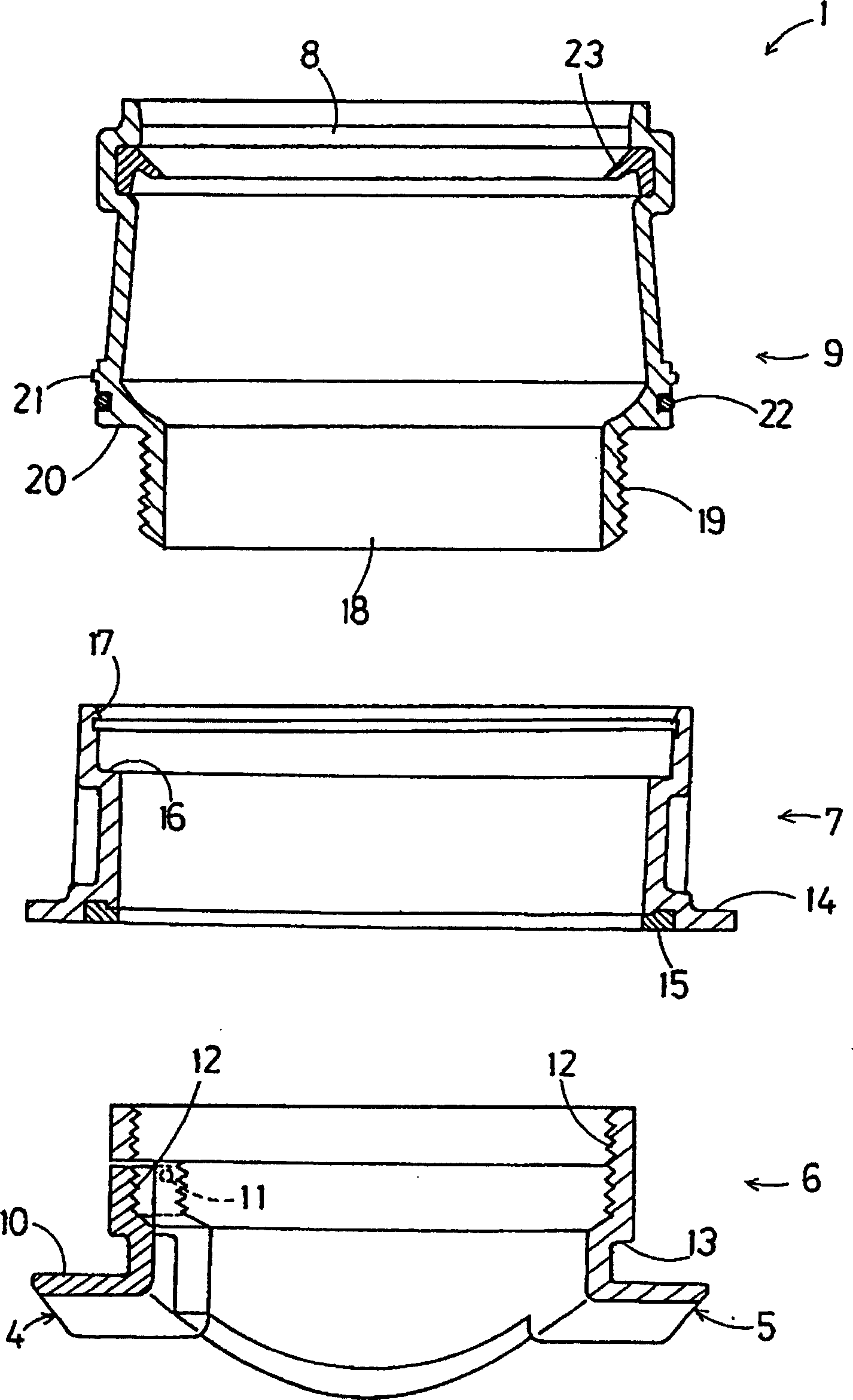
[0046] The connecting branch pipe 1 has: a locking part 6 provided with two locking claws 4 and 5 which lock the periphery of the opening part 3 of the sewer main pipe 2; 7; and a connecting part 9 inserted into the saddle part 7 and provided with a rubber ring socket 8 as a connecting port for connecting the installation pipe at the upper part.

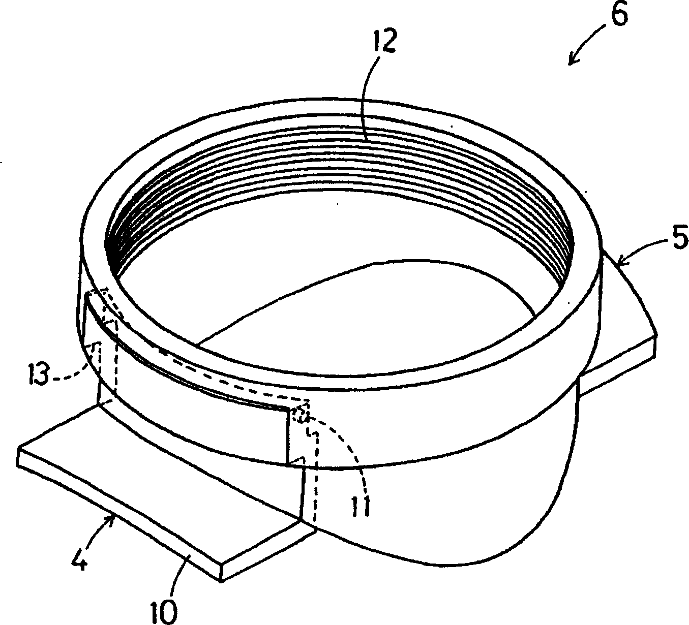
[0047] Such as figure 1 and figure 2 As shown, the cross-section of the two locking claws 4 and 5 of the locking member 6 is approximately L-shaped, and the shape of the locking plate 10 protruding substantially horizontally is a shape along the inner peripheral sur...

Embodiment 2

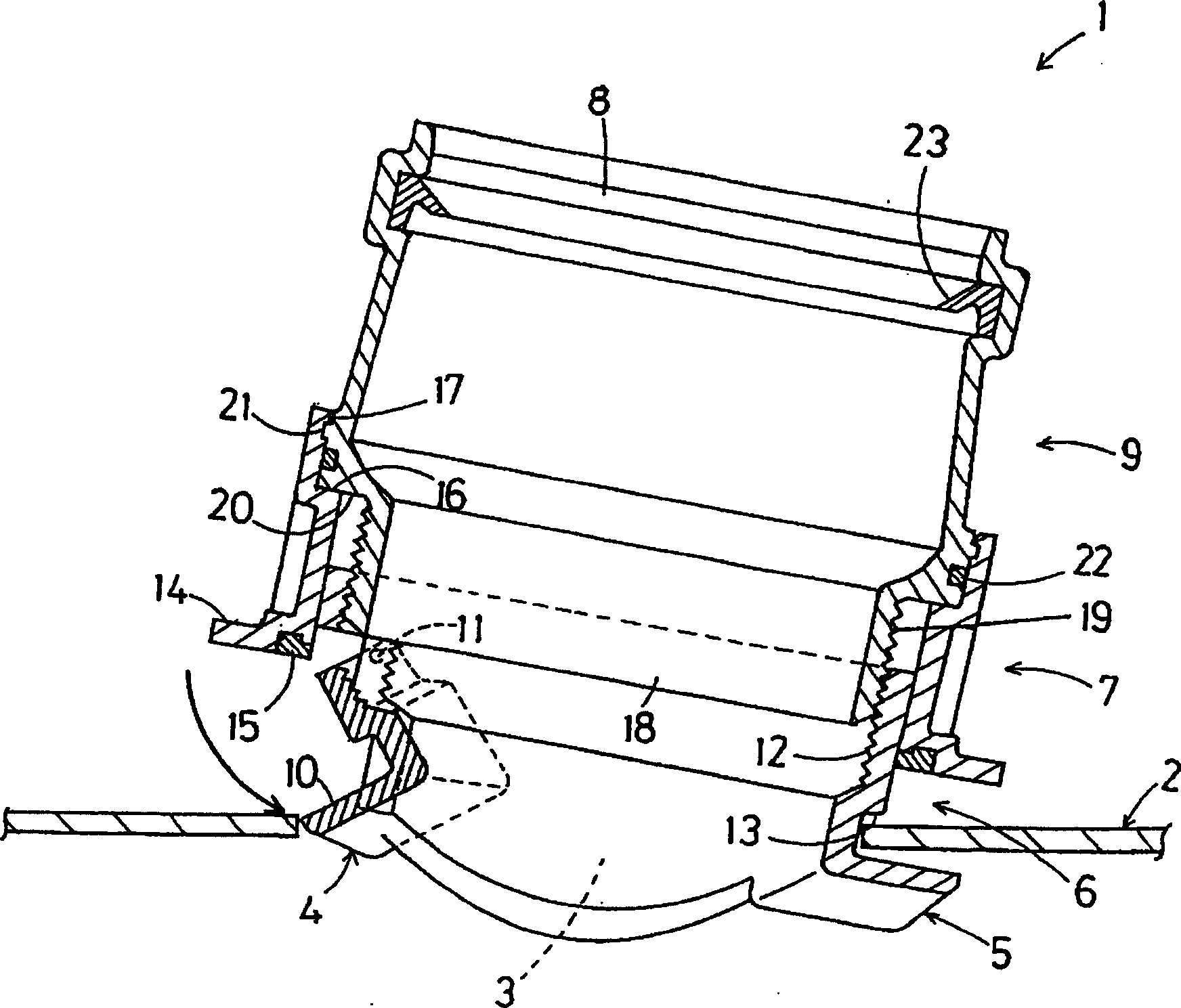
[0073] Figure 7 ~ Figure 12 represents another embodiment.

[0074] The connecting branch pipe 1 of this embodiment has: a locking part 6 provided with two locking claws 4 and 5 that are locked on the periphery of the opening part 3 of the sewer main pipe 2; The saddle part 7 above the sewer main pipe 2; and the connecting part 9 inserted in the saddle part 7 and provided with a rubber ring socket 8 as a connection port for connecting the installation pipe at the top.

[0075] Such as Figure 7 As shown, the cross section of the two locking claws 4 and 5 of the locking member 6 is roughly L-shaped, and the shape of the locking plate 10 protruding substantially horizontally is a shape along the inner peripheral surface of the opening 3 of the sewer main pipe 2. bow shape.

[0076] A pair of pivot pins 11 protrude from the side of the central part of one locking claw 4 , and the one locking claw 4 is rotatably pivoted to the locking member 6 through the pivot pins 11 . In a...


PUM


Abstract

To provide a connection branch pipe capable of improving the reliability of the execution, and achieving labor saving of the piping construction.The connection branch pipe 1 is comprised of a locking member 6 in which two locking pawls 4, 5 locked in the periphery of an opening 3 of a main drainage 2 are installed, a saddle member 7 fitted into the locking member 6 and installed on the main drainage 2, and a connecting member 9 inserted into the saddle member 7 and provided with a connection port 8 connected by an attached pipe. One locking pawl 4 is rotatably and pivotable attached to the locking member 6 via a pivot pin 11, the locking pawl 4 can pass the opening 3 of the main drainage 2 by revolving the pivotably attached locking pawl 4. The locking pawl 4 is prevented from revolving by screwing the connecting member 9 to the locking member 6, and the locking pawl 4 can not pass the opening 3 of the main drainage 2.

Description

technical field [0001] The invention relates to a connecting branch pipe used for connecting branch pipes such as installation pipes on a main pipe such as a sewer main pipe. Background technique [0002] Generally, when connecting the installation pipe connected to the common tank of each household to the main sewer pipe, when piping from the main sewer main pipe to the upstream side, a saddle-shaped branch pipe is installed at a predetermined position of the main sewer main pipe to branch the main sewer main pipe. Perform piping work to connect the branch pipe to the installation pipe. [0003] Then, when installing a branch pipe on the main sewer pipe, use a hole-opening machine (Holso-1) to open an opening at a predetermined position on the main sewer pipe, install a saddle-shaped branch pipe on the opening, and then use an adhesive on the main sewer pipe. Or paste cement to fix the branch. [0004] However, when using adhesives or pasty adhesives, it is difficult to s...

Claims


Application Information

Patent Timeline
IPC IPC(8): F16L41/00
CPCF16J15/02F16L17/032F16L41/14
Inventor 太田浩司桥诘稔
Owner ARONKASEI
Why Eureka
Try Eureka