
Output torque depulsation control method for switch reluctance servo motor

A technology of servo motor and switched reluctance, applied in torque ripple control, AC motor control, control system, etc., can solve the problems of difficulty in establishing torque sharing function accurately, unable to meet the current switching rate, affecting the effect of eliminating ripple, etc. Achieve high operational reliability and fault tolerance, wide practicability, and high cost performance

Inactive Publication Date: 2006-04-12
CHINA UNIV OF MINING & TECH
View PDF0 Cites 20 Cited by
  • Summary
  • Abstract
  • Description
  • Claims
  • Application Information

AI Technical Summary

Problems solved by technology

The second is to reduce the output torque ripple by optimizing the phase current waveform of the motor, mainly including: (a) Obtain the expected current waveform by querying the phase current / rotor position curve data under different torques obtained from the actual measurement, and reduce the torque ripple, but It cannot meet the requirement of infinite current switching rate during commutation; (b) use the torque sharing coefficient to obtain the torque of each phase, and obtain the expected current waveform from the motor torque angle characteristics to reduce torque ripple, but the torque sharing function is accurately established Difficult; (c) gradually establish the switched reluctance motor model through "self-learning", determine the expected current waveform online, and reduce the torque ripple, but it is difficult to obtain a more accurate motor model with less calculation, and the inaccuracy of the model will affect (d) By injecting current into the phase winding, a torque pulse is generated to offset the original torque ripple of the conventional power supply, but it is difficult to realize

Method used


Image

  • Output torque depulsation control method for switch reluctance servo motor
  • Output torque depulsation control method for switch reluctance servo motor
  • Output torque depulsation control method for switch reluctance servo motor

Examples


Embodiment 1

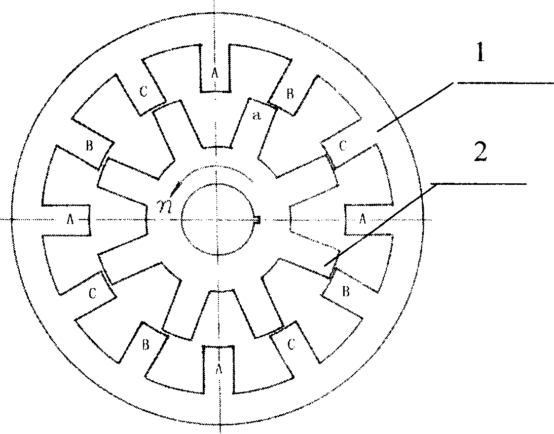
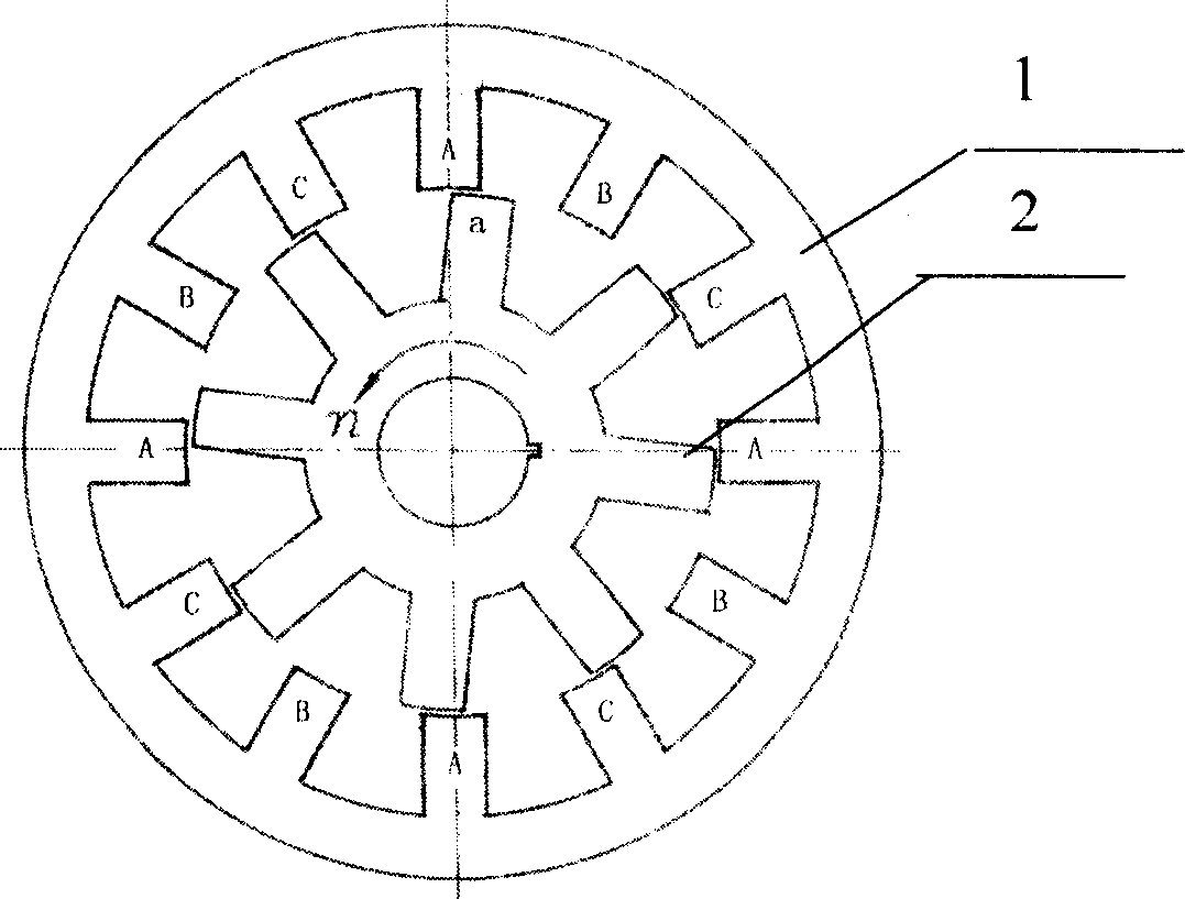
[0016] Embodiment 1: Taking a three-phase 12 / 8 structure switched reluctance servo motor as an example, figure 1 , 2 , 3 and 4, during the servo operation of rotor 2, when starting, it starts to supply power to the stator 1 phase winding of the switched reluctance servo motor at the position of the minimum phase inductance of 0°, and stops supplying power to the switched reluctance servo motor at the position of the maximum phase inductance of 22.5°. The stator 1 phase winding of the resistance servo motor is powered, the phase current chopping limit is fixed, and the phase current of the switched reluctance servo motor is chopped; during electric operation, the stator 1 of the switched reluctance servo motor starts at the minimum phase inductance position of 0° Phase winding power supply, stop supplying power to the switched reluctance servo motor stator 1-phase winding at 17.5° before the maximum phase inductance position, adjust the phase current chopping limit in time, and...

Embodiment 2

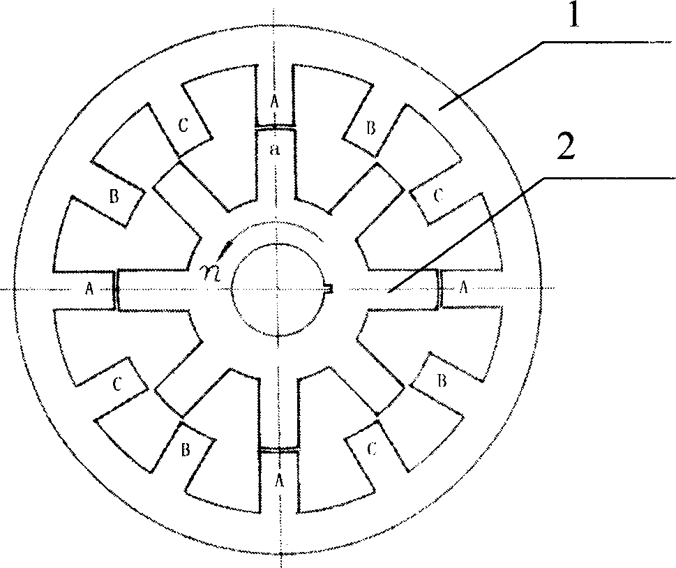
[0017] Embodiment 2: Taking the four-phase 8 / 6 structure switched reluctance servo motor as an example, Figure 5 , 6 As shown in , 7 and 8, during the servo operation of rotor 2, when starting, it starts to supply power to the stator 1 phase winding of the switched reluctance servo motor at the position of the minimum phase inductance of 0°, and stops supplying power to the switching reluctance servo motor at the position of 30° of the maximum phase inductance. The stator 1 phase winding of the resistance servo motor is powered, the phase current chopping limit is fixed, and the phase current of the switched reluctance servo motor is chopped; during electric operation, the stator 1 of the switched reluctance servo motor starts at the minimum phase inductance position of 0° Phase winding power supply, stop supplying power to the phase winding of the switched reluctance servo motor stator at 23° before the maximum phase inductance position, adjust the phase current chopping lim...


PUM


Abstract

This invention relates to a method for controlling the output torque pulse-extinction of a switch reluctance servomotor used in different phase numbers and structures. When starting the motor, it begins to supply the motor stator phase winding at the smallest phase inductance position and stops supplying it at the maximum position and fixes the chopper limit of the phase current, when operating, it begins to supply it at the smallest phase inductance position and stops supplying before hand at the maximum phase inductance position to regulate the chopper-limit of the phase current, when reducing the operation, it begins supplying the winding at the maximum position and stops it before hand at the minimum position to fix the chopper limit of the phase current.

Description

1. Technical field [0001] The invention relates to a control method for output torque ripple elimination of a switched reluctance servo motor, and is especially suitable for switched reluctance servo motors with various phase numbers and structures. 2. Background technology [0002] Since the switched reluctance motor adopts a simple and strong rotor structure with no brush, no winding, and no permanent magnet, and the unipolar power converter supplies unidirectional current excitation, the phases on the magnetic circuit can be independent of each other and the phases on the circuit can be independent of each other. Independent of each other, the system has high operational reliability and fault tolerance. Its natural mechanical characteristics are similar to series-excited DC motors, and its low-speed torque is large. The switched reluctance motor has many controllable parameters, and it is easy to realize the conversion of electric and braking operation in the control, an...

Claims


Application Information

Patent Timeline
IPC IPC(8): H02P6/10H02P25/098
Inventor 陈昊
Owner CHINA UNIV OF MINING & TECH
Features
  • Generate Ideas
  • Intellectual Property
  • Life Sciences
  • Materials
  • Tech Scout
  • Unparalleled Data Quality
  • Higher Quality Content
  • 60% Fewer Hallucinations
Learn More