Microminiature mobile robot system oriented to precise operation of micro electromechanical system
A technology of mobile robots and micro-electromechanical systems, applied in the field of robot systems, can solve problems such as difficult modular design, poor versatility, and large size
- Summary
- Abstract
- Description
- Claims
- Application Information
AI Technical Summary
Problems solved by technology
Method used
Image

Examples
specific Embodiment approach 1
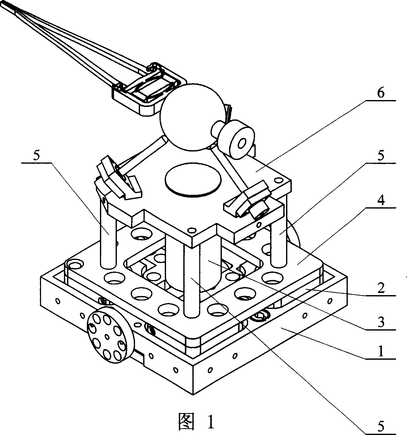
[0005] Specific embodiment one: (see Fig. 1) this embodiment is made up of macro-movement positioning unit 1, micro-movement positioning unit 2, torque motor 3, transition connecting plate 4, connecting column 5, micromanipulator unit 6: micro-movement positioning unit 2 Set in the macro mobile positioning unit 1, the transition connecting plate 4 is fixed on the upper side of the micro mobile positioning unit 2, the lower end of the connecting column 5 is fixedly connected with the upper side of the transition connecting plate 4, and the upper end of the connecting column 5 is connected to the micromanipulator The lower side of the unit 6 is fixedly connected, and the torque motor 3 is fixedly connected with the macro mobile positioning unit 1 .
specific Embodiment approach 2
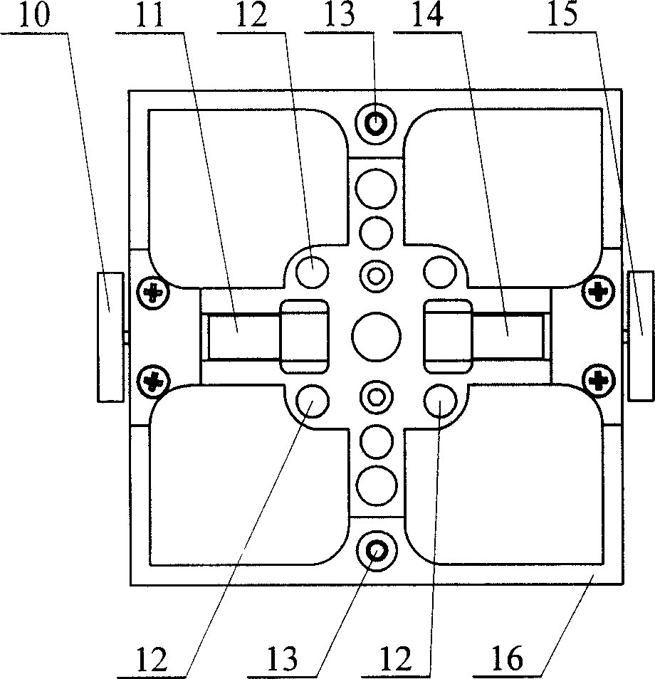
[0006] Specific implementation mode two: (referring to Fig. 1~ image 3 ) The macro mobile positioning unit 1 of the present embodiment is made up of a left drive wheel 10, a left micro motor 11, two height-adjustable support balls 13, a right micro motor 14, a right drive wheel 15 and a body 16; the left micro motor 11 and Right micro-motor 14 is symmetrically fixed on both sides in the body 16, left drive wheel 10 is fixed on the output shaft of left micro-motor 11, and right drive wheel 15 is fixed on the output shaft of right micro-motor 14, and two can adjust height The support ball 13 is arranged on the bottom of the body 16, and two support balls 13 that can be adjusted in height are vertically arranged with the left drive wheel 10 and the right drive wheel 15, and the body 16 has a through hole 12. This embodiment adopts a symmetrical structure, and the center of two miniature SMOOVY motors is symmetrically installed on both sides to drive the robot to achieve all-roun...
specific Embodiment approach 3
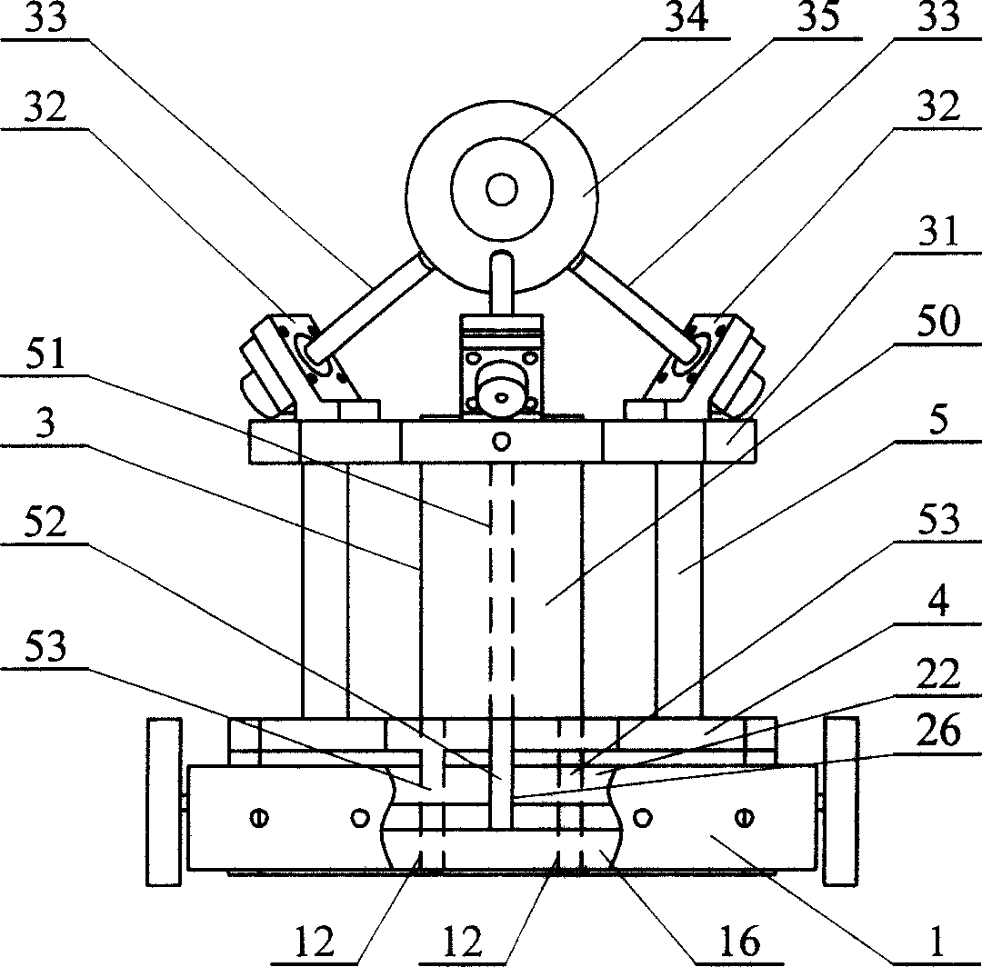
[0007] Specific embodiment three: (referring to Fig. 1, Figure 4 , Figure 5 ) The micro-movement positioning unit 2 of the present embodiment consists of a mobile platform 20, a preload screw 21, a flexible beam 22, a first electromagnet B1, a second electromagnet B2, a third electromagnet A1, a fourth electromagnet A2, a first electromagnet Composed of piezoelectric ceramics I, second piezoelectric ceramics II, third piezoelectric ceramics III and fourth piezoelectric ceramics IV; the mobile platform 20 is formed by wire cutting as a whole, and is cut into four parts in the four corners of the mobile platform 20 The electromagnet holes 23 and four pairs of elliptical hinges 24 distributed in a "ten" shape, the flexible beam 22 is arranged in the middle of the mobile platform 20, the inside of the four corners of the flexible beam 22 has guide holes 25, and the center of the flexible beam 22 has a threaded hole 26. The first electromagnet B1, the second electromagnet B2, th...
PUM
 Abstract
Description
Claims
Application Information
 - R&D
- Intellectual Property
- Life Sciences
- Materials
- Tech Scout
- Unparalleled Data Quality
- Higher Quality Content
- 60% Fewer Hallucinations
Browse by: Latest US Patents, China's latest patents, Technical Efficacy Thesaurus, Application Domain, Technology Topic, Popular Technical Reports.
© 2025 PatSnap. All rights reserved.Legal|Privacy policy|Modern Slavery Act Transparency Statement|Sitemap|About US| Contact US: help@patsnap.com