Electric boosting system for of smelting kiln of glass furnace

An electric fluxing and glass technology, applied in glass furnace equipment, glass production, glass manufacturing equipment, etc., can solve problems such as radiant heat control and molten glass defects

Inactive Publication Date: 2006-04-26
SAMSUNG CORNING CO LTD
View PDF0 Cites 18 Cited by
  • Summary
  • Abstract
  • Description
  • Claims
  • Application Information

AI Technical Summary

Problems solved by technology

However, it is difficult to control the radiant heat in several zones, causing the problem that defects will appear in the molten glass

Method used


Image

  • Electric boosting system for of smelting kiln of glass furnace
  • Electric boosting system for of smelting kiln of glass furnace
  • Electric boosting system for of smelting kiln of glass furnace

Examples


Embodiment Construction

[0015] Preferred embodiments of the present invention will now be described in detail with reference to the accompanying drawings, in which, Figure 1 to Figure 3 The same components are denoted by the same reference numerals.

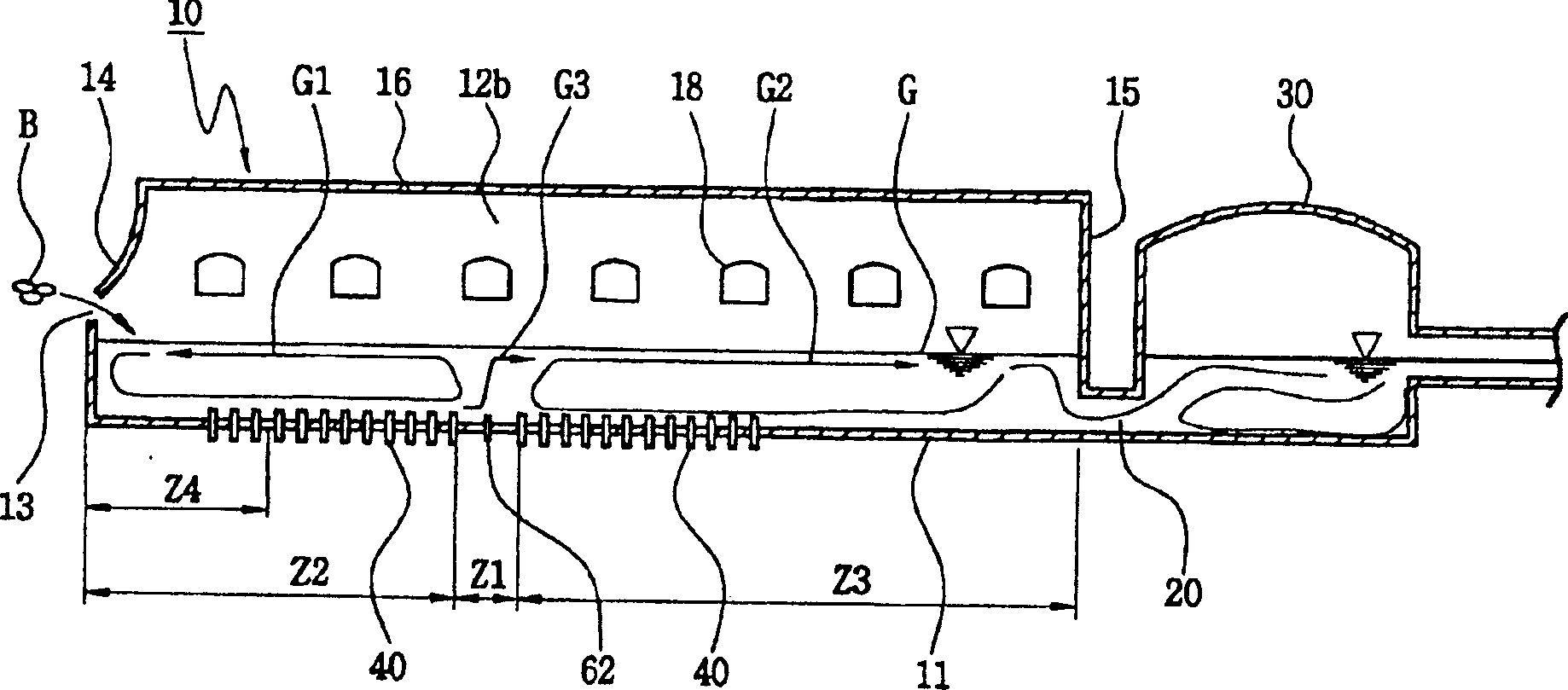
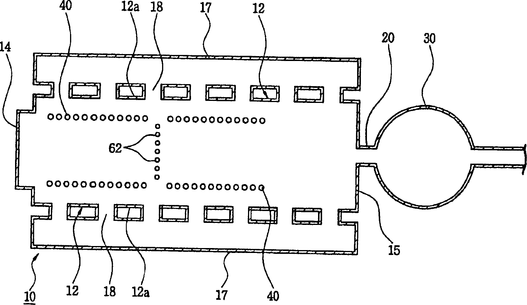
[0016] refer to figure 1 and figure 2 , according to a preferred embodiment of the present invention, the glass melting furnace includes: a melting furnace 10, which is used to melt the glass raw materials B put into it; Glass G; a refining chamber 30 connected to the downstream end of the throat 20 for removing bubbles generated inside the molten glass G and homogenizing the molten glass G.

[0017] The melting furnace 10 is composed of a bottom 11, a side wall 12, a rear wall 14, a front wall 15 and a vaulted top 16, wherein the rear wall 14 has a feeding port 13 through which glass raw material B is put into the melting furnace 10, and the front The wall 15 acts as a boundary between the furnace 10 and the throat 20 . Each side wall 12 has a si...


PUM


Abstract

An electric boosting system comprising a plurality of molybdenum electrode rods for generating resistive heat of molten glass and a power source connected to the molybdenum electrode rods for power required to operate the molybdenum electrode rods Applied to molybdenum electrode rods. The molybdenum electrode rods are arranged in the heating zone and the cooling zone, are arranged on the bottom of the melting furnace and are installed along two opposite side ends of the melting furnace bottom so as to face each other.

Description

technical field [0001] The present invention relates to a melting furnace of a glass melting furnace; more particularly, to an electric boosting system for a melting furnace of a glass melting furnace, which provides molten glass production by generating resistive heat of molten glass. The heat required for the feed. Background technique [0002] It is well known to manufacture screens and funnels for cathode ray tubes by press forming a piece of molten glass, called a gob, which is produced by melting glass raw material, called a batch, in a glass melting furnace. The glass melting furnace includes: a melting furnace, which is used to melt glass raw material to produce molten glass; a furnace throat, which is used to discharge molten glass from the melting furnace; and a refining chamber, which is used to provide molten glass without bubbles and homogeneous components a plurality of homogenization chambers for providing molten glass homogenized ...

Claims


Application Information

Patent Timeline
Patent Type & Authority Applications(China)
IPC IPC(8): C03B5/02C03B5/027C03B5/16C03B5/193
CPCY02P40/57
Inventor 梁在翊柳政宇金容洙崔棕淳郑清薰
Owner SAMSUNG CORNING CO LTD
Why Eureka
Try Eureka