Method for hardware accelerated anti-aliasing in 3D

A polygonal, geometrical shape technique used in computing to solve problems of varying quality and performance, excessive amount of time, object bloat, etc.

Inactive Publication Date: 2006-04-26
MICROSOFT CORP
View PDF0 Cites 1 Cited by
  • Summary
  • Abstract
  • Description
  • Claims
  • Application Information

AI Technical Summary

Problems solved by technology

Current techniques for anti-aliasing rasterization of 3D models either require an excessive amount of time, be supported by dedicated hardware, or re

Method used


Image

  • Method for hardware accelerated anti-aliasing in 3D
  • Method for hardware accelerated anti-aliasing in 3D
  • Method for hardware accelerated anti-aliasing in 3D

Examples


Embodiment Construction

[0013] Exemplary Operating Environment

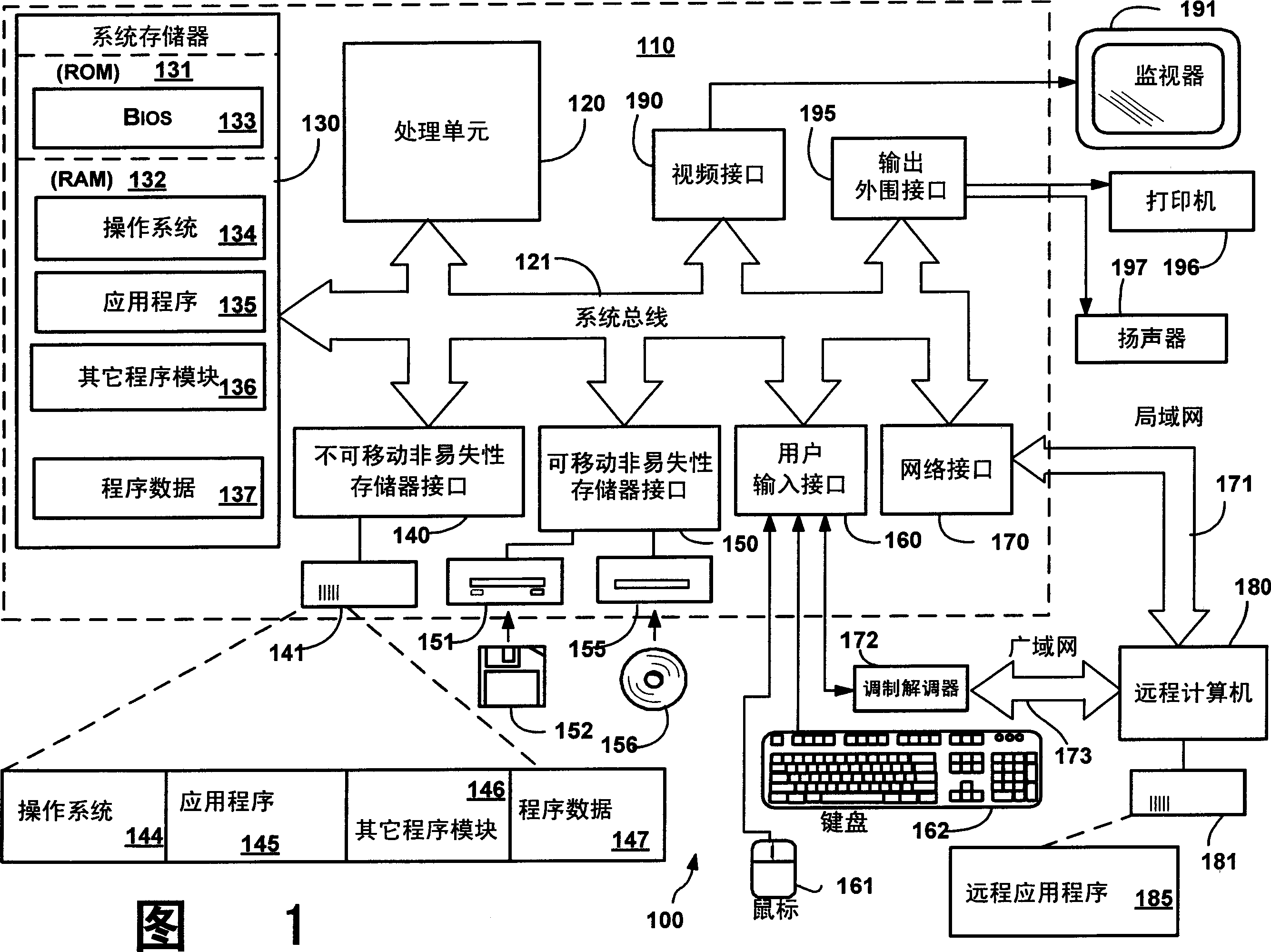
[0014] Figure 1 illustrates an example of a suitable computing system environment 100 upon which the present invention may be implemented. Computing system environment 100 is only one example of a suitable computing environment and is not intended to suggest any limitation as to the scope of use or functionality of the invention. Neither should the computing environment 100 be interpreted as having any dependency or requirement relating to any one or combination of components illustrated in the exemplary operating environment 100 .

[0015] The invention is operational with numerous other general purpose or special purpose computing system environments or configurations. Examples of well-known computing systems, environments, and / or configurations suitable for use in the present invention include, but are not limited to, personal computers, server computers, handheld or laptop devices, multiprocessor systems, microprocessor-based sys...


PUM


Abstract

A method and system for anti-aliasing rasterization of objects. From a specific viewpoint of the object represented by the graph, select a shape with edges on the outline of the object. Creates edge geometry on the edges of shapes that lie on the outline of an object. Renders the edge geometry. Either render the shape after rendering the edge geometry using the depth tester such that no parts of the shape are allowed to overlap the edge geometry, or modify the shape itself to remove any parts that overlap the edge geometry. This can be repeated for each side of each shape that lies on the outline of the object.

Description

technical field [0001] This invention relates generally to computers and more particularly to graphics. Background technique [0002] Anti-aliasing is used to reduce the artifacts typical of slanted or curved edges in computer graphics. Current techniques for anti-aliasing rasterization of 3D models either require an excessive amount of time, the support of dedicated hardware, or result in unacceptable typical artifacts, such as object bloat. Also, anti-aliasing for 3D models varies in quality and performance between graphics cards. There is a need for an anti-aliasing method for accelerating 3D models. Ideally, such an approach would provide consistent results across different graphics cards. Contents of the invention [0003] Briefly, the present invention provides methods and systems for anti-aliasing rasterization of objects. From a particular viewpoint of the object represented by the shape, a shape is selected that has edges on the outline of the object. Creates...

Claims


Application Information

Patent Timeline
IPC IPC(8): G06T15/50
CPCG06T11/40G06T15/503G06T3/00G06T15/10
Inventor A·史蒂文森A·A·米沙尔
Owner MICROSOFT CORP
Why Eureka
Try Eureka