Apparatus and method for drafting

A technique of illuminating device, axis direction, applied in the field of drawing device

Inactive Publication Date: 2006-05-10
MITSUBISHI RAYON CO LTD
View PDF1 Cites 4 Cited by
  • Summary
  • Abstract
  • Description
  • Claims
  • Application Information

AI Technical Summary

Problems solved by technology

Therefore, the method of improving the brightness of the light exit surface area near the light incident end surface of the light guide and making the defects in this area less obvious is adopted. H

Method used


Image

  • Apparatus and method for drafting
  • Apparatus and method for drafting
  • Apparatus and method for drafting

Examples


Embodiment Construction

[0131] The structure of the present invention will be described in detail below with reference to the accompanying drawings.

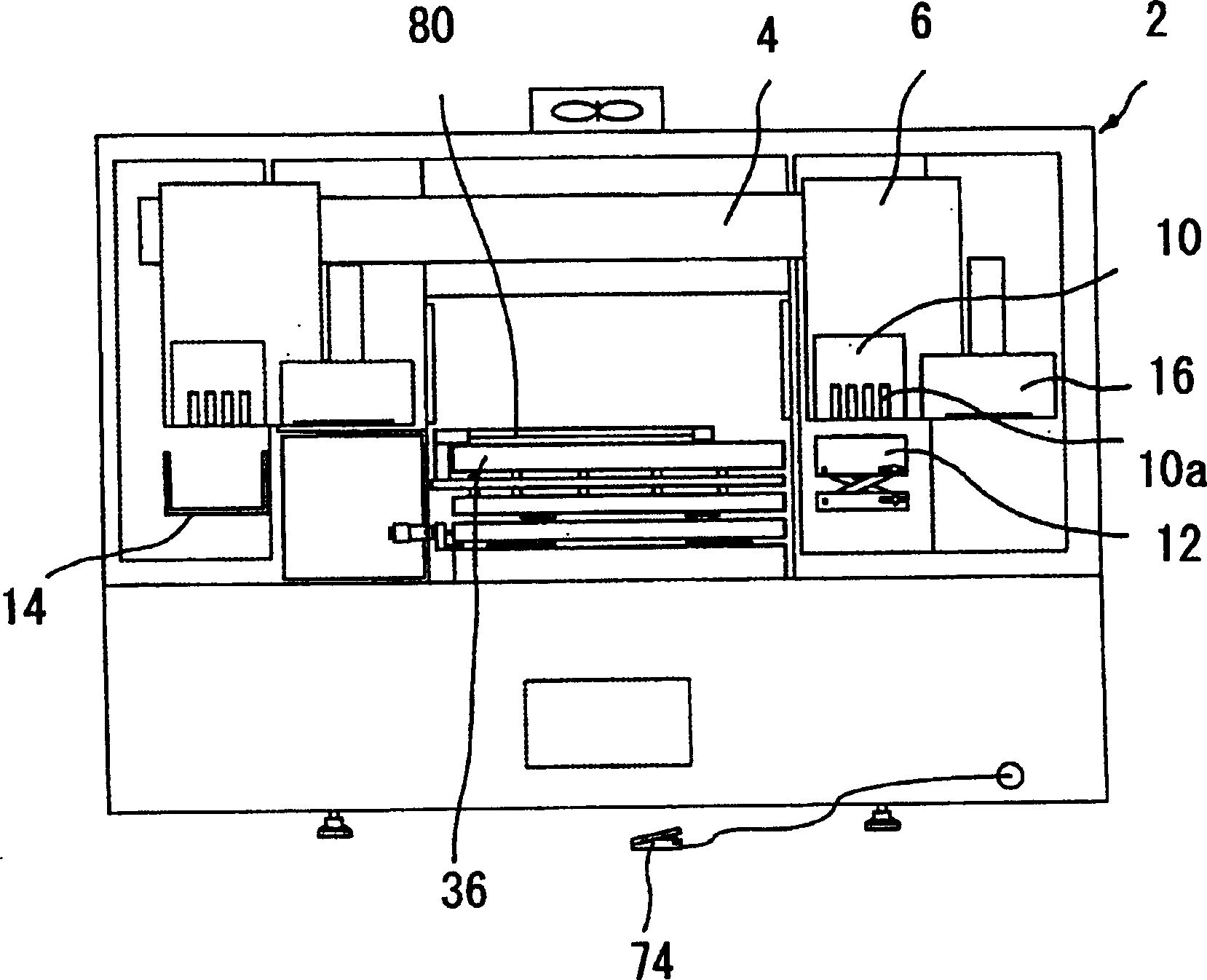
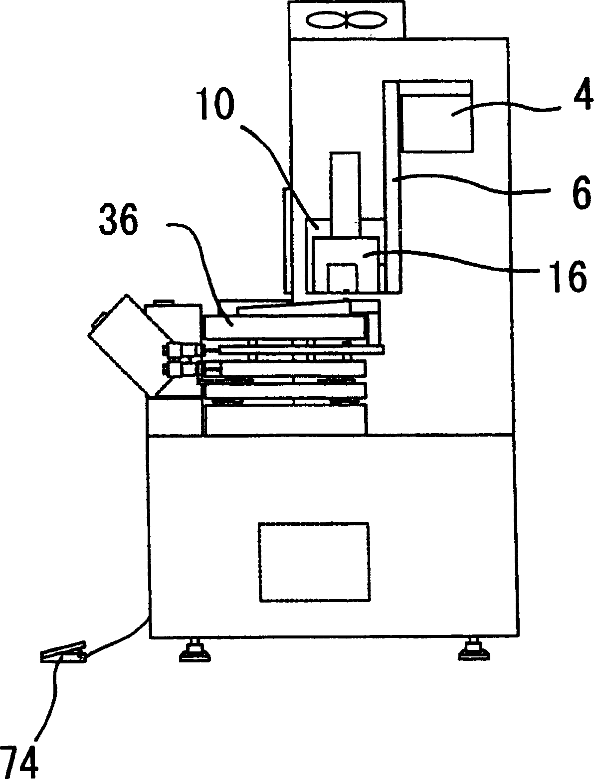
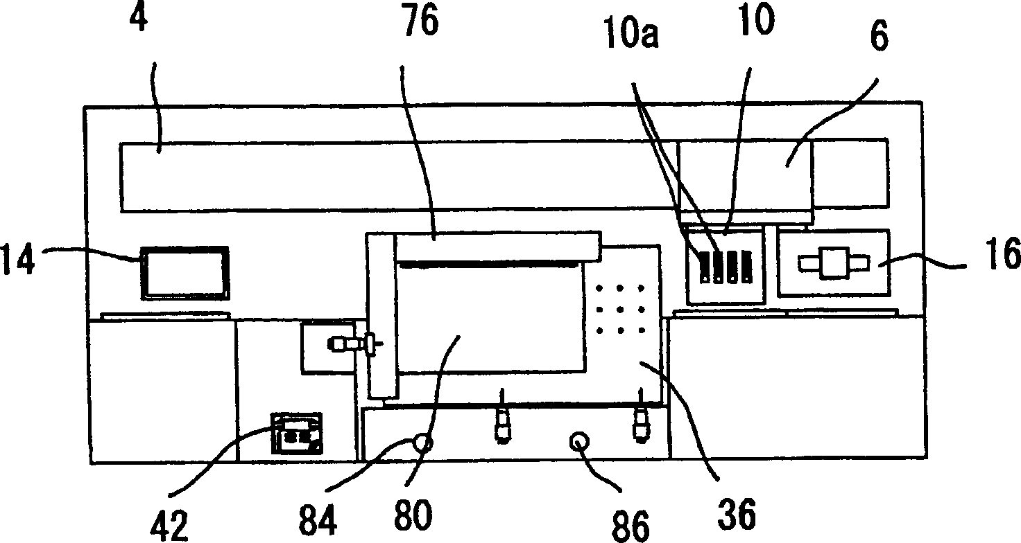
[0132] figure 1 , figure 2 , image 3 An overall schematic diagram showing the drawing device of the present invention. On the body of the plotter 2, a rail-shaped head guide member 4 extending in the Y-axis direction is supported horizontally with respect to the ground. On the print head guide part 4, the Y-axis driving mechanism (Y-axis driving manipulator) 8 (refer to Figure 19 ) is equipped with a carriage 6 in such a way that the carriage 6 is connected to a head 10 carrying a plurality of inkjet print heads 10a. On both ends of the above-mentioned print head guide member 4, located outside the printing area, the standby position of the above-mentioned head 10 is set, and the ink jet of the print head 10a is arranged in a liftable manner at one of the print head standby positions. Part 12 is a capping part for plugging.

[0133] In the ot...


PUM

PropertyMeasurementUnit
Viscosityaaaaaaaaaa
Surface tensionaaaaaaaaaa

Abstract

The object of the present invention is to provide a drawing device for printing lines on a medium with good production efficiency and high-precision printing. The body of the drawing device includes a head (10) carrying a printing head (10a) and a supporting platform (36). The medium (80) on the support table (36) is printed by the printing head (10a) of the head (10). One of the head (10) and the support table (36) is assembled on the fuselage in a movable manner relative to the other through a transmission mechanism. When the other side is assembled on the fuselage, it does not pass through the transmission mechanism. One of the two XY axes moves in the direction of the axis, while the other does not move in the direction of the axis.

Description

technical field [0001] The present invention relates to a drawing device for precisely printing fine lines or the like on a medium such as a light guide used in an edge-illuminated surface light source device constituting a liquid crystal display device used as a display unit in a notebook computer, a liquid crystal television, etc. and drawing methods. Specifically, it relates to a drawing device and a drawing method especially suitable for making a light guide for an edge-illuminated surface light source device in which it is desired to prevent bright lines appearing in the light exit surface area near the light entrance end surface facing the main light source. Background technique [0002] In recent years, liquid crystal display devices have been widely used in various other fields as monitors of portable notebook computers and the like, and as display units of liquid crystal televisions and video display integrated liquid crystal television...

Claims


Application Information

Patent Timeline
IPC IPC(8): G02F1/1335B41J2/07
Inventor 野崎义人山下友义佐伯厚志丹野康二高桥真也山口真安达惠二
Owner MITSUBISHI RAYON CO LTD
Why Eureka
Try Eureka