

Non-linear pulse-width modulation PWM control device
A pulse width modulation and control device technology, which is applied in lighting devices, electric lamp circuit layout, use of semiconductor lamps, etc., can solve the problems of dynamic compression of visual response, lack of network arbitration protocol, and inability to achieve human vision. Expanding the dynamic range and enhancing the intuitive feel
- Summary
- Abstract
- Description
- Claims
- Application Information
AI Technical Summary
Problems solved by technology
Method used
Image

Examples
Embodiment Construction
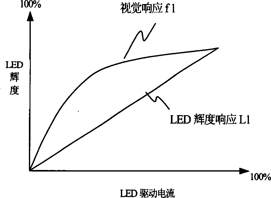
[0028] see figure 1 : Indicates the visual defects shown by the current semiconductor LED lighting current relative to the visual response of the human eye. Among them, the horizontal axis represents the linear current change of the driving semiconductor LED, and the vertical axis represents the luminance change of the semiconductor LED with the change of the driving current. It can be seen from this that the LED luminance response L1 is a linear response with the linear change of the driving LED current, while the human eye The visual response f1 to the linear current change of the semiconductor LED shows a nonlinear change characteristic of the logarithmic response; this is the visual defect caused by the human eye.
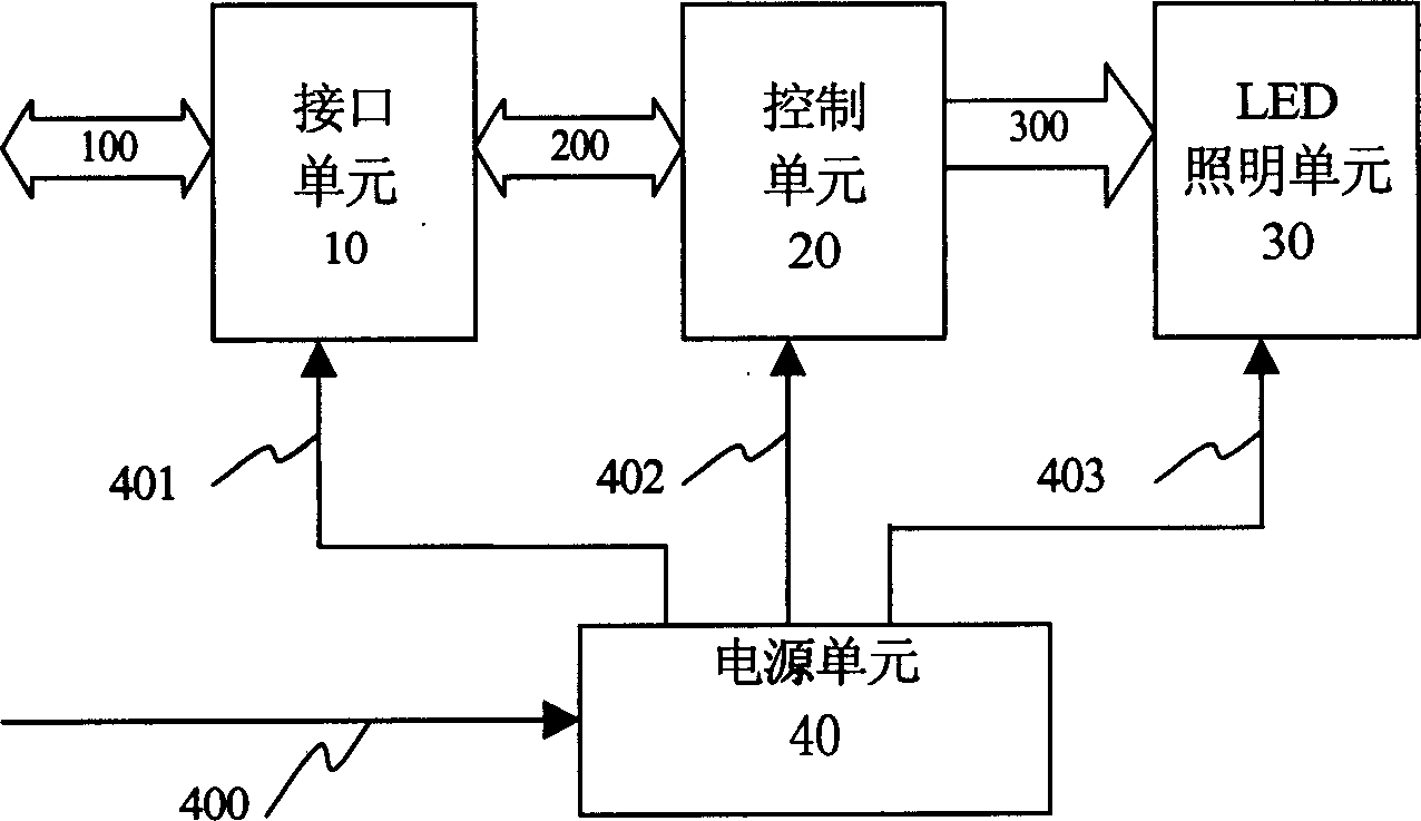
[0029] see figure 2 , figure 2 It is a principle block diagram of the present invention, and the present invention consists of interface unit 10, LED lighting bright unit 30 and will interface unit 10, LED lighting unit 30 respectively connected t...
PUM
 Abstract
Description
Claims
Application Information