Heat pump system for treating cold area after sewage-primary sewage

A technology for heat pump systems in cold areas, applied in heat pumps, sustainable biological treatment, biological water/sewage treatment, etc. The effect of high utilization efficiency, fast heat conduction and large energy efficiency ratio

Inactive Publication Date: 2006-05-17
HARBIN INST OF TECH
View PDF0 Cites 6 Cited by
  • Summary
  • Abstract
  • Description
  • Claims
  • Application Information

AI Technical Summary

Problems solved by technology

[0004] The present invention has the following beneficial effects: 1. The present invention applies a sewage heat pump system with a three-stage shower condenser to the sewage treatment system to heat raw sewage. On the one hand, it can solve biological problems in cold regions, cold months or special occasions Solve the problem of low water temperature in sewage; on the other hand, fully recycle the heat energy in sewage, saving additional energy for heating sludge, sewage and aeration. It coincides with the time, and both belong to low-grade heat energy, the energy utilization efficiency is high, the energy efficiency ratio of the heat pump system is large, and energy waste is avoided, so the present invention has significant economic and social benefits

Method used


Image

  • Heat pump system for treating cold area after sewage-primary sewage
  • Heat pump system for treating cold area after sewage-primary sewage
  • Heat pump system for treating cold area after sewage-primary sewage

Examples


specific Embodiment approach 1

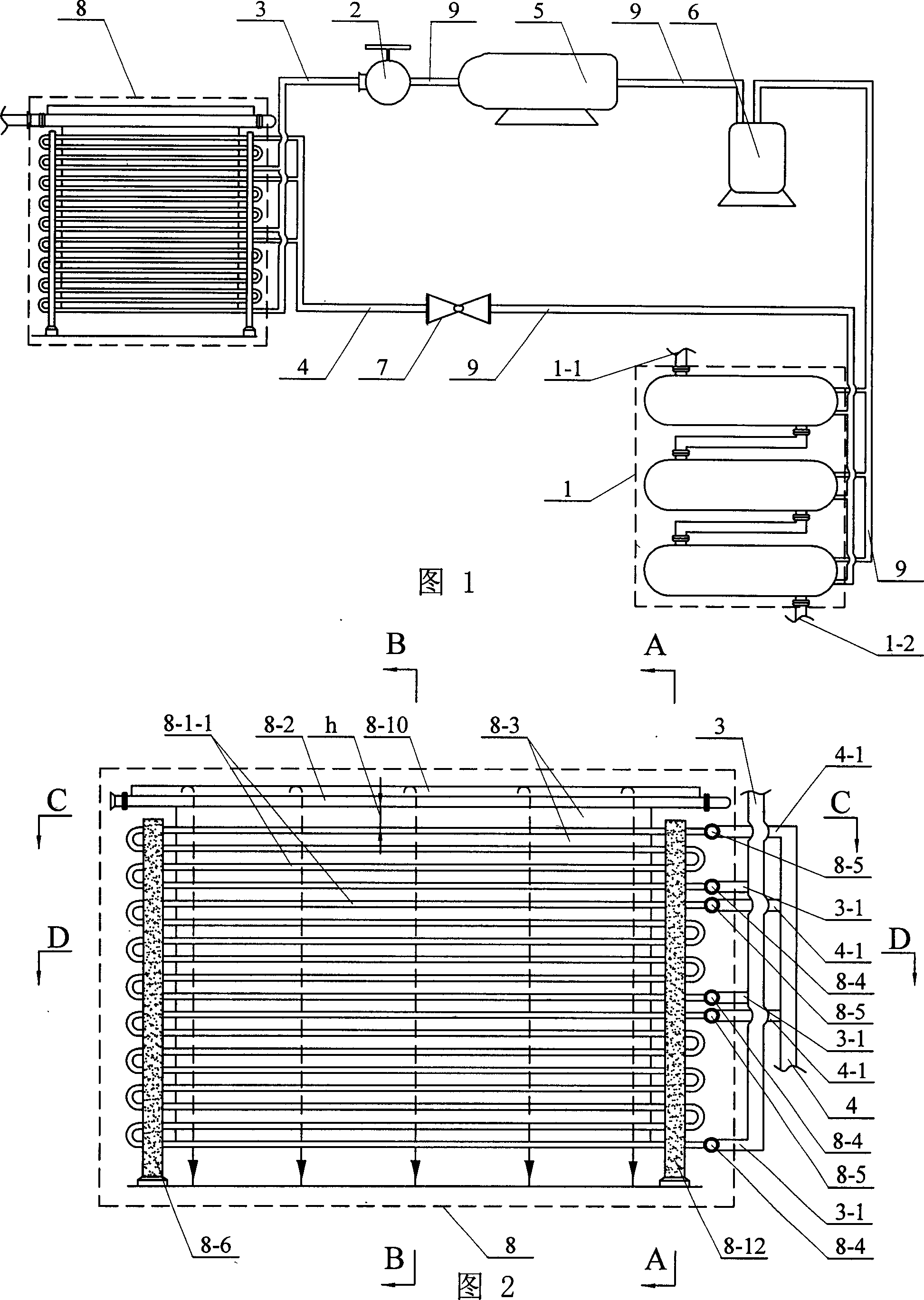
[0006] Specific Embodiment 1: This embodiment is described in conjunction with FIG. 1. This embodiment consists of a three-stage shell-and-tube evaporator 1, a check valve 2, a refrigerant inlet pipeline 3, a refrigerant outlet pipeline 4, a compressor 5, a gas The liquid separator 6, the expansion valve 7, the three-stage shower condenser 8, and the refrigerant pipeline 9 are composed; the outlet end of the compressor 5 is fixedly connected with the inlet end of the one-way valve 2 through the refrigerant pipeline 9, and the one-way The outlet end of the valve 2 is fixedly connected to the inlet end of the three-stage shower condenser 8 through the refrigerant inlet pipeline 3, and the outlet end of the three-stage shower condenser 8 is connected to the expansion valve 7 through the refrigerant outlet pipeline 4. The inlet end is fixedly connected, the outlet end of the expansion valve 7 is fixedly connected to the inlet end of the evaporator 1 through the refrigerant pipeline...

specific Embodiment approach 2

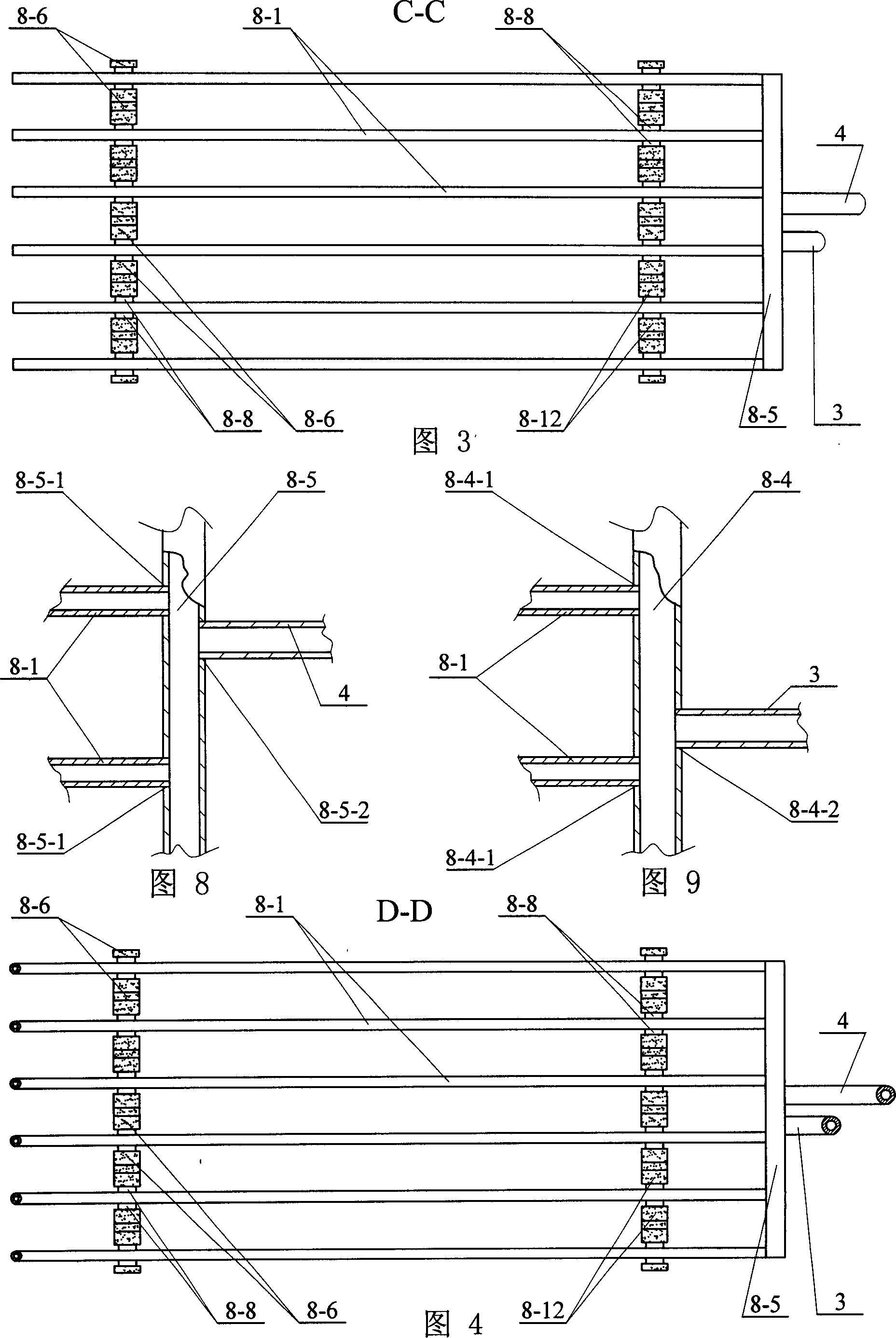
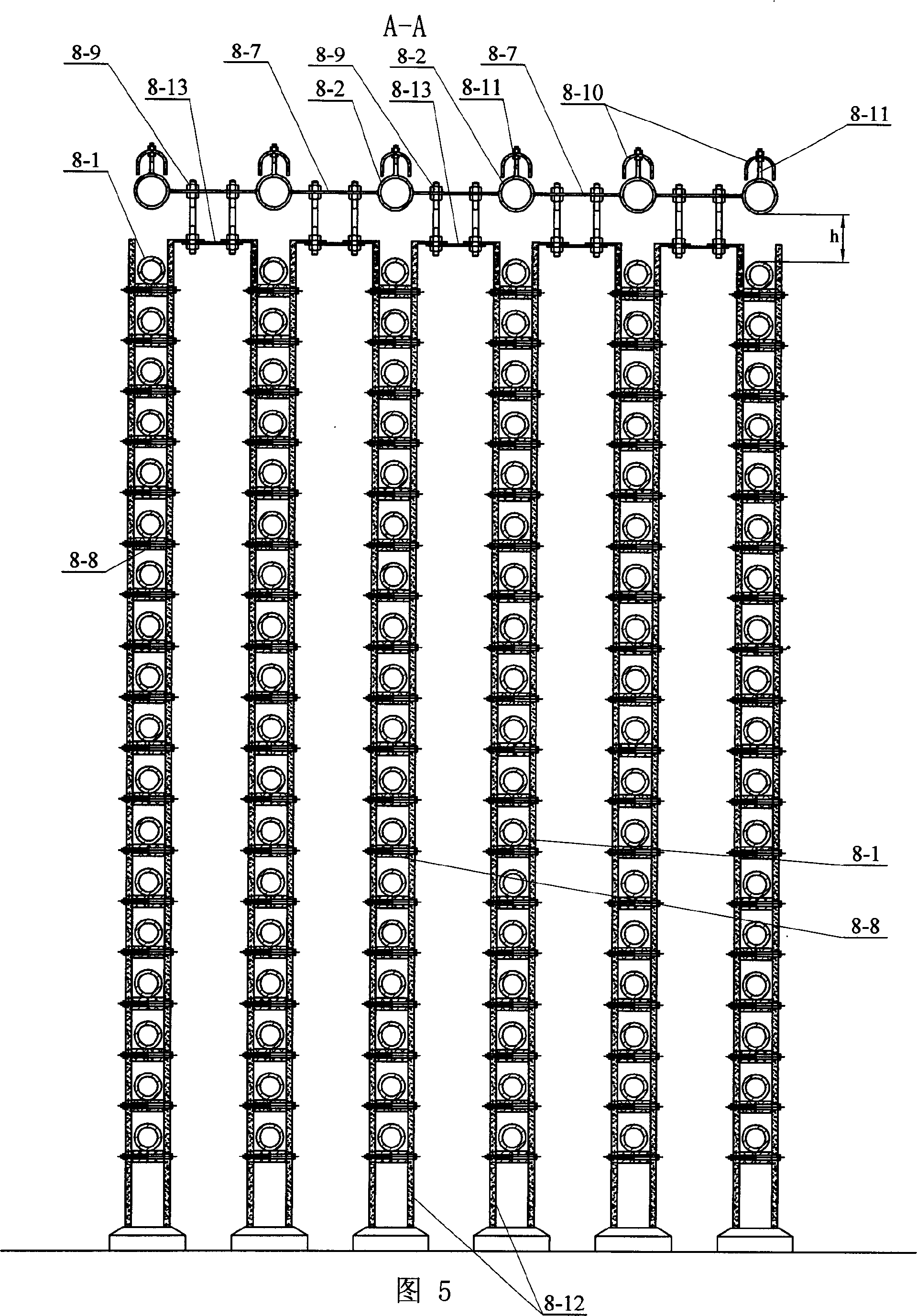
[0007] Specific embodiment two: in conjunction with Fig. 2, Fig. 3, Fig. 4, Fig. 5, Image 6 , Fig. 8 and Fig. 9 illustrate the present embodiment, the three-stage shower condenser 8 of the present embodiment consists of a group of spray coils placed side by side, a water shower 8-2, a dripping plate 8-3, and a liquid separator 8 -4. Composed of liquid collecting pipe 8-5, bracket, connecting frame 8-7, bracket spacing adjustment device 8-8, and connector 8-9; each row of spray coils 8-1 is respectively installed in the corresponding bracket, Each horizontal pipe 8-1-1 on the spray coil 8-1 of each column is installed on the bracket spacing adjustment device 8-8 respectively, and the two ends of the bracket spacing adjustment device 8-8 are connected with the bracket respectively. There is a shower pipe 8-2 above the shower snake pipe 8-1, and the distance between the top of each row of shower snake pipe 8-1 and the bottom end of the corresponding shower pipe 8-2 is h, and the ...

specific Embodiment approach 3

[0009] Specific embodiment three: This embodiment is described in conjunction with Fig. 2, Fig. 3, and Fig. 4. The difference between this embodiment and specific embodiment two is: the bracket of this embodiment is composed of a left bracket 8-6 and a right bracket 8-12 ; The left end of each row of spray coils 8-1 is fixed in the corresponding left bracket 8-6, the right end of each row of spray coils 8-1 is fixed in the corresponding right bracket 8-12, and the left bracket 8-6 On the outer wall of the bottom end of the shower pipe 8-2 between the right bracket 8-12 and on the outer wall of the bottom end of each horizontal pipe 8-1-1 on each row of spray coils 8-1, they are respectively fixedly connected along the axial direction There are 8-3 drop plates. The left bracket 8-6 and the right bracket 8-12 are used to fix each row of spray coils 8-1, which has the advantages of firm fixing and easy installation and disassembly.

[0010] Embodiment 4: This embodiment is descr...


PUM

PropertyMeasurementUnit
pore sizeaaaaaaaaaa

Abstract

The present invention relates to a sewage heating system of sewage treatment plant. Said system is characterized by that the invented compressor is fixedly connected with non-return valve by means of refrigerant pipeline, the non-return valve is fixedly connected with three-stage shower-cooled condenser by means of refrigerant inlet pipeline, the three-stage shower-cooled condenser is fixedly connected with expansion valve by means of refrigerant outlet pipeline, said expansion valve is fixedly connected with evaporator by means of refrigerant pipeline, the evaporator is fixedly connected with gas-liquid separator by means of refrigerant pipeline, and said gas-liquid separator is fixedly connected with compressor by means of refrigerant pipeline. The treated sewage heat energy can be recovered and reutilized.

Description

technical field [0001] The invention relates to a sewage heating system of a sewage treatment plant, in particular to a treated sewage-primary sewage heat pump system in cold regions. Background technique [0002] The most commonly used sewage treatment process in most sewage treatment plants in my country is the traditional activated sludge process. The activated sludge method is a kind of sewage biological treatment method, and the sewage water temperature is the most important factor affecting the sewage biological treatment effect. Comprehensive studies have shown that the most suitable temperature range for sewage biological treatment is 25-35°C, and the sewage temperature of sewage treatment places such as pharmaceutical factories and breweries is often required to be higher. In order to meet the temperature requirements of sewage treatment, the following measures are often taken in some cities in northern my country: (1) The walls of aeration tanks, secondary sedimen...

Claims


Application Information

Patent Timeline
Patent Type & Authority Applications(China)
IPC IPC(8): F25B30/06C02F3/12
CPCY02W10/10
Inventor 姚杨姜益强马最良宋艳
Owner HARBIN INST OF TECH
Why Eureka
Try Eureka