Internal exhaust recirculation method for an internal combustion engine

A technology of internal combustion engine and exhaust gas emission, which is applied in the direction of exhaust gas recirculation, internal combustion piston engine, combustion engine, etc., to achieve the effects of reduced fuel consumption rate, high exhaust gas recirculation rate and excellent effect

Inactive Publication Date: 2006-05-17
FEV MOTORENTECHN GMBH
View PDF2 Cites 9 Cited by
  • Summary
  • Abstract
  • Description
  • Claims
  • Application Information

AI Technical Summary

Problems solved by technology

However this only allows for modest EGR rates at full load

Method used


Image

  • Internal exhaust recirculation method for an internal combustion engine
  • Internal exhaust recirculation method for an internal combustion engine
  • Internal exhaust recirculation method for an internal combustion engine

Examples


Embodiment Construction

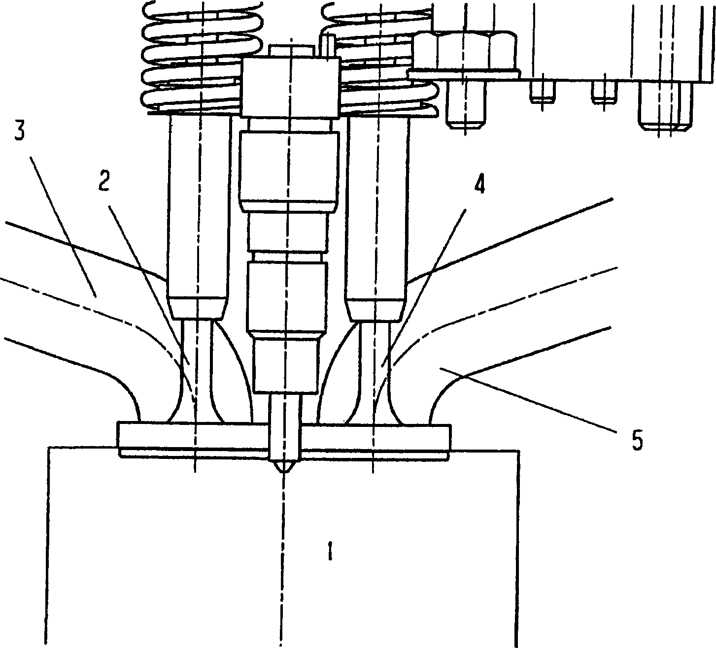
[0032] figure 1 It shows that the cylinder 1 among the multiple cylinders of the four-stroke internal combustion engine can be connected with the intake pipe 3 through the intake valve 2 for inhaling fresh air, and connected with the exhaust pipe 5 through the exhaust valve 4 for exhaust gas discharge.

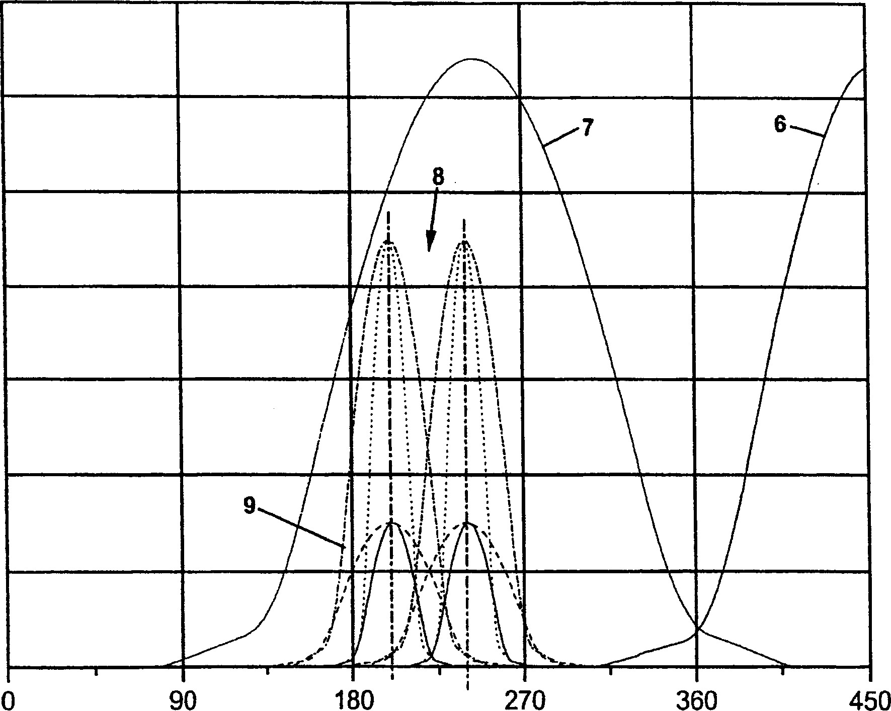
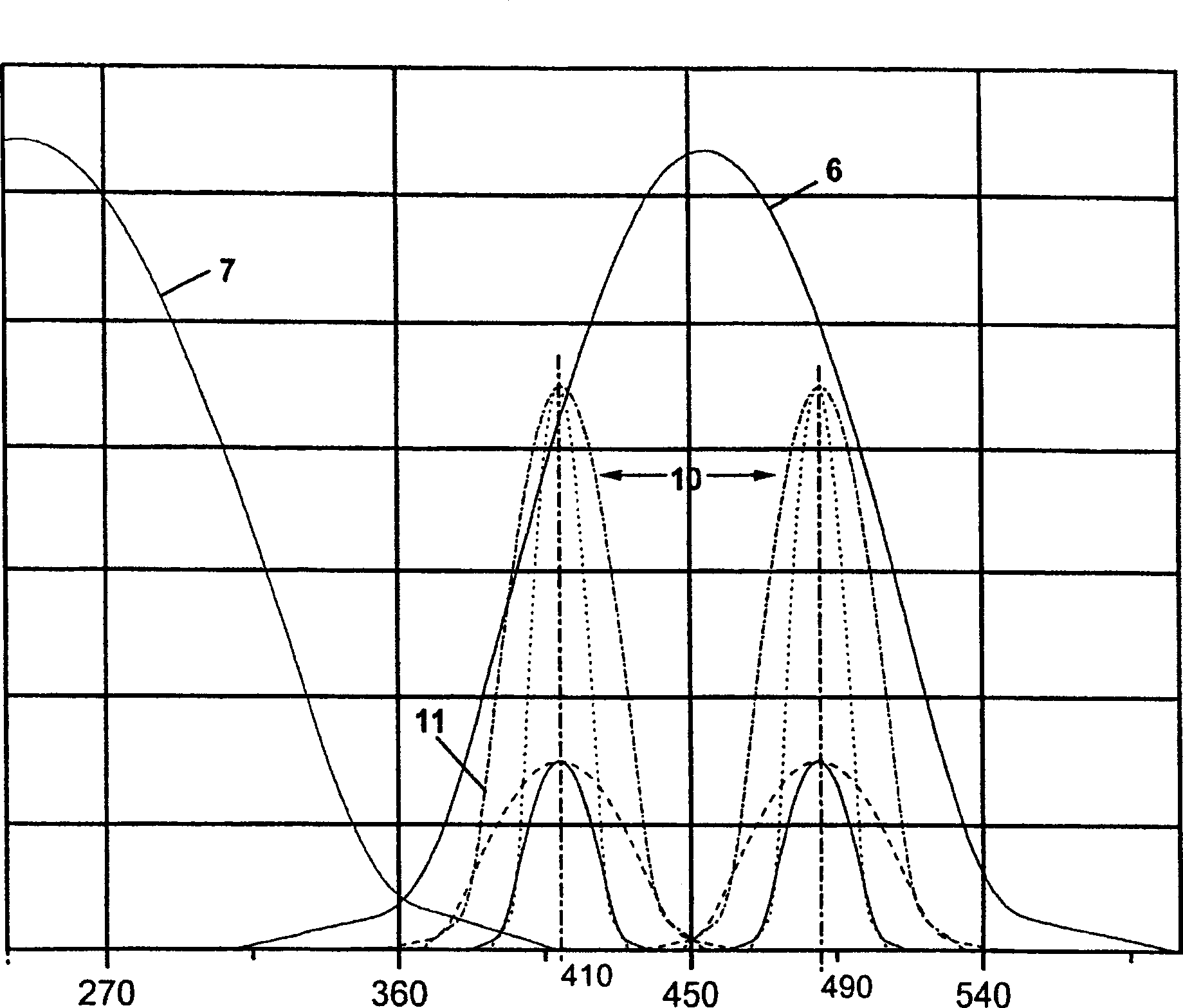
[0033] An internal combustion engine sequentially undergoes an intake stroke, a compression stroke, a combustion stroke, and an exhaust stroke, where the exhaust and intake strokes represent gas exchange. For this purpose, the valves 2, 4 are periodically actuated in known manner, in particular under camshaft control. During intake, figure 2 The partially shown valve lift curve 6 represents the intake valve 2, during exhaust the valve lift curve 7 represents the exhaust valve 4; the two valve lift curves 6, 7 can be superimposed on each other in a known manner, so that Exhaust gases are completely expelled from cylinder 1.

[0034] For internal exhaust gas recirculation, the...


PUM


Abstract

The invention relates to the internal exhaust-gas recirculation in an internal combustion engine with gas exchange valves periodically controlled by a camshaft ( 22 ) in accordance with the four-stroke principle, in which, during the gas exchange exhausting of exhaust gas from the respective cylinder ( 1 ) into the exhaust duct ( 5 ), an intake valve ( 2 ) associated with the respective cylinder ( 1 ) is open in a crank angle range after top dead center of the ignition of the gas mixture present in the cylinder ( 1 ), in order to exhaust part of the exhaust gas into an intake duct ( 3 ), so that during the next gas exchange intake both fresh gas and exhaust gas are taken in from the intake duct ( 3 ), the respective intake valve ( 2 ) being actuated during the gas exchange exhausting independently of the periodic gas exchange intake, and the additional opening of the respective intake valve ( 2 ) being carried out in the range from 110 to 150% of the opening angle of the start of opening of the exhaust duct ( 5 ) by the exhaust valve ( 4 ).

Description

technical field [0001] The invention relates to a method for internal exhaust gas recirculation and a correspondingly designed internal combustion engine. Background technique [0002] Worldwide, the requirements for the purity of the exhaust gases of internal combustion engines are being increasingly and more stringently governed by regulations. One can satisfy these with NO x Methods with emission-related requirements include the use of internal exhaust gas recirculation. This involves mixing a certain amount of exhaust gas with fresh air within the cylinders of the internal combustion engine prior to ignition. Considerable reductions in NO can be achieved if optimized mixing ratios are used x emissions. [0003] In order to generate the above-mentioned mixture, the German patent document DE 34 01 362 C2 discloses a method for internal exhaust gas recirculation in internal combustion engines with gas exchange valves periodically controlled by the camshaft according to ...

Claims


Application Information

Patent Timeline
Patent Type & Authority Applications(China)
IPC IPC(8): F02D21/08F02B47/08F02D13/02F02M25/07
CPCF02B47/08F02D13/0207F02D13/0253F02D13/0273F02D13/0276F02D21/08F02M26/01Y02T10/12
Inventor 乔肯·米勒伯恩德·基尔舍马库斯·杜斯曼伊诺·洛斯
Owner FEV MOTORENTECHN GMBH
Why Eureka
Try Eureka