Cavity member for hollow slab

A technology of hollow slabs and cavities, applied to building components, on-site preparation of building components, floor slabs, etc., can solve the problems of high damage rate of cavity components, increased construction costs, inconvenient handling and construction, etc.

Inactive Publication Date: 2006-05-24
湖南邱则有专利战略策划有限公司
View PDF3 Cites 1 Cited by
  • Summary
  • Abstract
  • Description
  • Claims
  • Application Information

AI Technical Summary

Problems solved by technology

However, during the handling and construction of such cavity components, the structural bottom plate is prone to breakage, so the damage rate of the cavity components is high, and the handling and construction are inconvenient, which increases the construction cost.

Method used


Image

  • Cavity member for hollow slab
  • Cavity member for hollow slab
  • Cavity member for hollow slab

Examples


Embodiment Construction

[0065] The present invention will be further described below in conjunction with the accompanying drawings and embodiments.

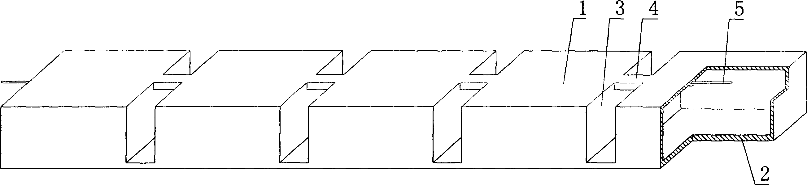
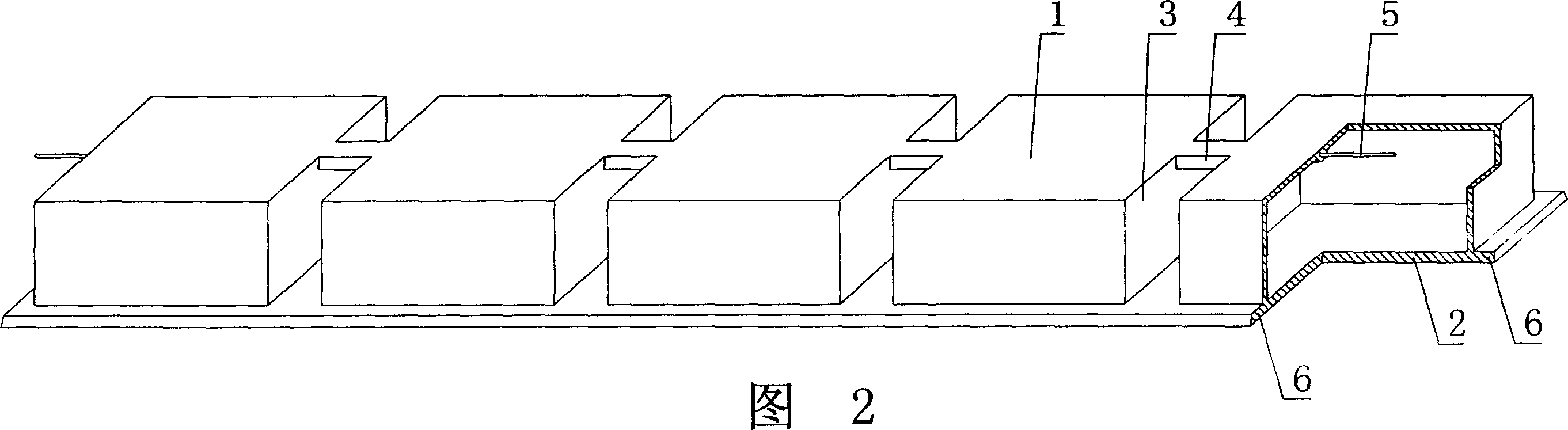
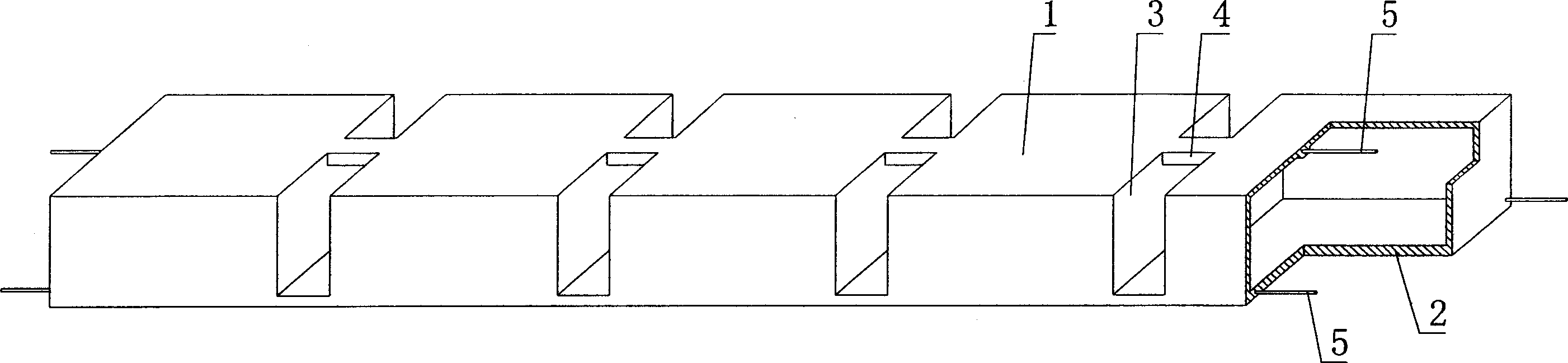
[0066] As shown in the accompanying drawings, the present invention includes a cavity formwork 1 and a structural bottom plate 2. The cavity formwork 1 and the structural bottom plate 2 are connected as a whole, and at least two or more cavity formworks 1 are arranged alternately on the structural bottom plate 2. The interphase cavity between the cavity formwork 1 and the structural bottom plate 2 constitute the inner rib cavity 3 of the cast-in-place structure. The cavity formworks 1 are connected to each other, the cavity formworks 1 are arranged longitudinally on the coaxial line, and at least one non-prestressed or prestressed steel bar, steel wire or steel strand 5 passes through at least two braces 4 and at least three The cavity mold shells 1 are connected to each other as a whole. In each accompanying drawing, 1 is a cavity formwork, 2 is a str...


PUM


Abstract

A cavity member for hollow plate includes integrated hollow form shell and structure bottom plate, wherein at least two hollow form shells alternatively arranged on structure bottom plate, the cavity of hollow form shell and structure bottom plate forms in site casting inner rib form cavity, it featuring said inner rib form cavity having at least one support-draw piece to connect adjacent hollow form shell, the hollow firm shell arranged in same longitudinal axis, at least one non-prestressed or prestressed steel bar, steel wire or steel strand integrally penetrating at least two support-draw pieces. Said invention has fine strength, rigidity and shock resistance, can be widely used in site casting reinforced steel concrete or prestressed reinforced steel concrete hollow plate, hollow storied building cover, room cover, base bottom plate, wall, and hollow bridge.

Description

(1) Technical field [0001] The present invention relates to a cavity member for a hollow plate. (2) Background technology [0002] At present, most of the buildings with brick-concrete structure and reinforced concrete structure use prefabricated hollow slabs as floor slabs. This floor slab has the advantages of fast construction speed and low cost. However, because there is no firm connection between two adjacent prefabricated hollow slabs, only cement mortar is used to fill the joints, so the integrity is poor, which is not conducive to earthquake resistance, and cracks and water seepage often occur in the gaps. In order to solve the above problems, many buildings adopt the method of cast-in-place concrete floor slabs (solid and hollow). Although the problems of earthquake resistance and cracking have been solved, a large number of templates are used during construction, which not only increases the cost, but also slows down the construction speed and prolongs the construc...

Claims


Application Information

Patent Timeline
Patent Type & Authority Applications(China)
IPC IPC(8): E04G15/06E04B5/36E04C5/01
Inventor 邱则有
Owner 湖南邱则有专利战略策划有限公司
Why Eureka
Try Eureka