Image processing system for mounting to a vehicle
An image processing device and image processing technology, applied in the field of vehicle systems, can solve problems such as increased power consumption, difficulty in real-time processing, time-consuming processing of action or measurement data, etc., and achieve high responsiveness and energy-saving effects
- Summary
- Abstract
- Description
- Claims
- Application Information
AI Technical Summary
Problems solved by technology
Method used
Image
Examples
no. 2 Embodiment
[0084] Next, a mode (second embodiment) in which the image processing area is further limited on the lower limit side in the vertical direction where radar scanning is not performed will be described. Note that descriptions of the same structures as those of the first embodiment will be omitted below.
[0085] In this example, between step S10 and step S11 in the aforementioned series of processing of FIG. 7 , the image processing apparatus 3 executes the following processing.
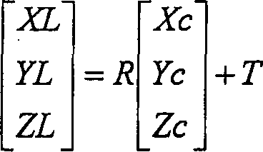
[0086] First, assume a plane 11 parallel to the road surface on which the own vehicle is running (for example, the tire contact plane itself on which the own vehicle is running, or a plane obtained by shifting the plane vertically and parallelly by a predetermined amount). For example, when the camera 1 is parallel to the vehicle body (tire ground plane), in the camera coordinate system (Xc, Yc, Zc), the data of the coordinate Xc in the height direction (for example, the distance from the tire ground p...
no. 3 Embodiment
[0090] Next, as shown in FIG. 12 , a method of reducing the size of the image processing area (expansion of the beam cross section) as the distance to the object measured by the radar 2 increases (third embodiment) will be described.
[0091] In this example, in step S3 of the aforementioned series of processes in FIG. 7 , the image processing device 3 executes, for example, any one of the following processes (1) to (3).
[0092] (1) According to the relational expression represented by the formula 4, the beam path length is changed according to the data of the distance ZL obtained in step S2 as the measurement result of the radar. In Equation 4, a represents the beam radius before the change, a' represents the beam radius after the change, d represents the distance data as a reference, and d' represents the distance data as a measurement result (see Fig. 12(A), (B) ). In addition, K represents a constant for adjustment.
[0093] [Equation 4]
[0094] a ...
no. 4 Embodiment
[0104] Next, a method of correcting the position of the image processing region based on the angle formed by the central axis of the radar 2 and the camera 1 (fourth embodiment) will be described.
[0105]In this example, the image processing apparatus 3 executes correction processing described below, for example, between steps S2 and S3 in the series of processing of FIG. 7 described above.
[0106] That is, when the angle formed by the vertical direction of the central axis of the radar 2 and the camera 1 is the offset angle dθ (refer to FIG. "H" is changed to "H+ZL×tan(dθ)".
[0107] As shown in FIG. 13(A), when setting the coordinate transformation formula in the state where the central axes of the radar 2 and the camera 1 are parallel, as long as the central axes of the radar 2 and the camera 1 are kept parallel, the position of the beam area ( That is, the position of the image processing area) can maintain the appropriate state as shown in FIG. 13(B). However, as show...
PUM
 Abstract
Description
Claims
Application Information
 - R&D
- Intellectual Property
- Life Sciences
- Materials
- Tech Scout
- Unparalleled Data Quality
- Higher Quality Content
- 60% Fewer Hallucinations
Browse by: Latest US Patents, China's latest patents, Technical Efficacy Thesaurus, Application Domain, Technology Topic, Popular Technical Reports.
© 2025 PatSnap. All rights reserved.Legal|Privacy policy|Modern Slavery Act Transparency Statement|Sitemap|About US| Contact US: help@patsnap.com


