Apparatus and method for manufacturing fluorescent tubes

A technology for manufacturing devices and manufacturing methods, which is applied in the field of fluorescent lamp manufacturing devices, can solve problems such as difficult operation compatibility and good efficiency, improve work efficiency and process efficiency, simplify the internal structure of the chamber, improve work efficiency and Effect

Inactive Publication Date: 2006-05-31
WEIHAI DMS OPTICAL ELECTROMECHANICAL CO LTD
View PDF0 Cites 2 Cited by
  • Summary
  • Abstract
  • Description
  • Claims
  • Application Information

AI Technical Summary

Problems solved by technology

Therefore, it is difficult to expect operational compatibility and good efficiency through its

Method used


Image

  • Apparatus and method for manufacturing fluorescent tubes
  • Apparatus and method for manufacturing fluorescent tubes
  • Apparatus and method for manufacturing fluorescent tubes

Examples


Embodiment Construction

[0033] Specific embodiments of the present invention will be described in detail below in conjunction with the accompanying drawings.

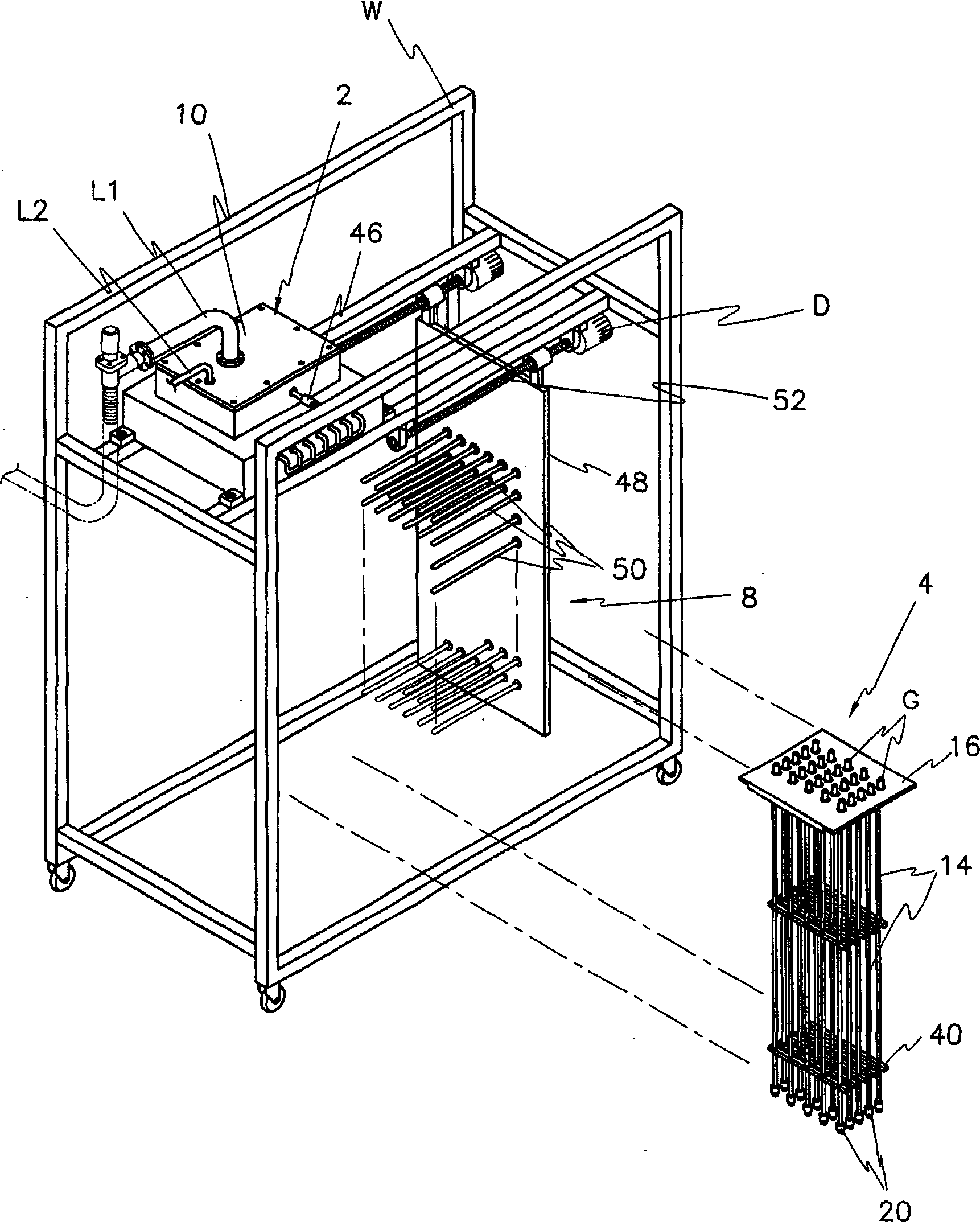
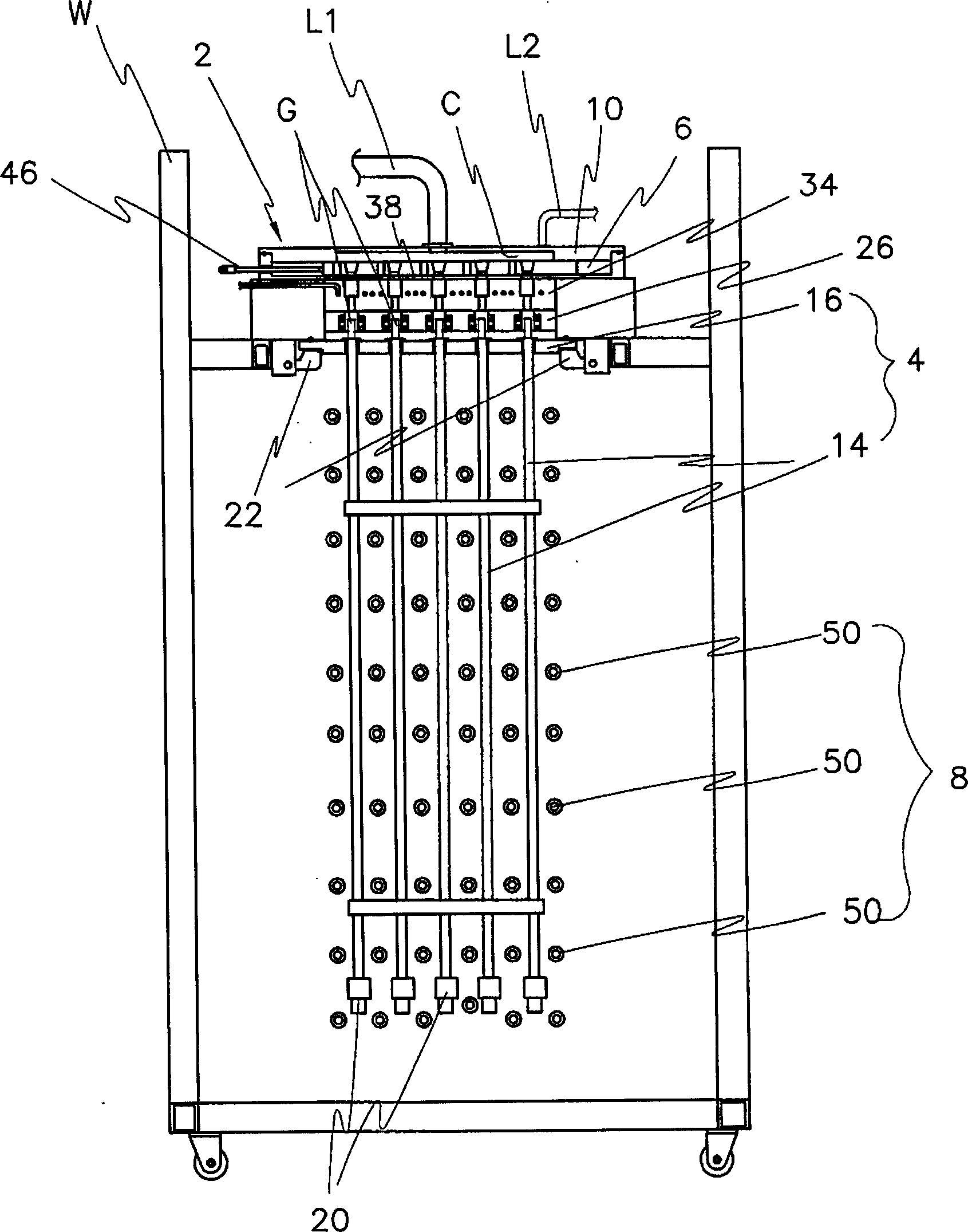
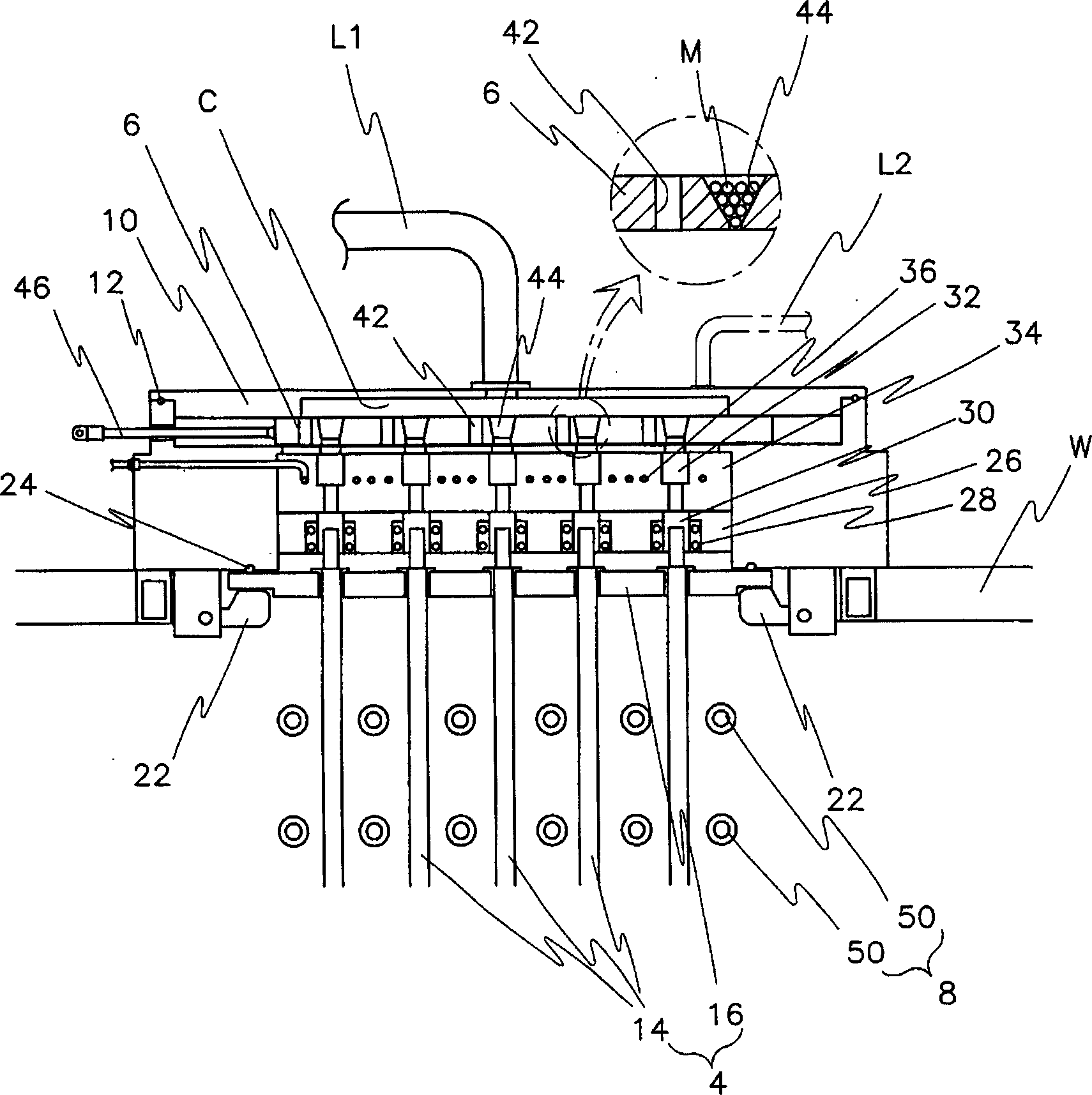
[0034] like figure 1 , figure 2 and image 3 As shown, the fluorescent lamp manufacturing device of the present invention includes: a chamber 2 having a processing space C that can be exhausted and injected into gas and mercury for manufacturing lamp tubes; the processing space C corresponding to the chamber 2 can be At the same time, a loading box 4 for at least two glass tubes G is provided in a detachable manner; an adjusting device 6 for converting the chamber 2 into a gas that can discharge the inside of the processing space C, and can inject gas and mercury.

[0035] The chamber 2 can be made of metal with good durability, corrosion resistance, chemical resistance and heat resistance, such as figure 1 As shown, the chamber 2 is in the shape of a stage-shaped box, and its interior is provided with such image 3 The processing space C...


PUM


Abstract

An apparatus for manufacturing a fluorescent lamp includes a chamber defining a process space, a cassette disposed corresponding to the process space of the chamber and loaded with a plurality of glass tubes, and a control unit for selectively connecting the process space of the chamber to a selective one of an exhaust hole, a gas injection hole, and a mercury injection hole to selectively perform exhaust, gas injection, and mercury injection processes.

Description

technical field [0001] The present invention relates to an apparatus and method for easily manufacturing fluorescent lamps, and in particular to an apparatus and method for manufacturing fluorescent lamps capable of mass-producing fluorescent lamps equipped with external electrodes with a simple process. Background technique [0002] Generally, a cold cathode fluorescent lamp (CCFL: Cold Cathode Fluorescent Lamp) is a glass tube coated with a phosphor on the inner wall and a certain amount of gas and mercury for making the fluorescent lamp emit light are sealed, and two electrodes are arranged inside the two ends of the glass tube. And constituted. [0003] The luminous principle of the fluorescent lamp is that when a high voltage is applied to the two electrodes, the electrons present in the glass tube move toward the electrode (positive electrode), and during the movement, the electrons collide with each other to generate secondary electrons discharge. The flowing electr...

Claims


Application Information

Patent Timeline
IPC IPC(8): H01J9/00H01J9/38H01J9/40
CPCH01J9/245H01J9/385H01J9/395H01J61/20H01J61/361H01J65/046
Inventor 李永哲
Owner WEIHAI DMS OPTICAL ELECTROMECHANICAL CO LTD
Why Eureka
Try Eureka