X-ray calculation tomographic scanner and x-ray detecting system
A detection system and ray technology, applied in computerized tomography scanners, echo tomography, etc., can solve the problem of increased space for the detection system, and achieve the effects of improving image quality, high stability, and reducing radiation noise
- Summary
- Abstract
- Description
- Claims
- Application Information
AI Technical Summary
Problems solved by technology
Method used
Image

Examples
no. 1 example
[0046] Refer below Figure 1-9 The first embodiment will be described.
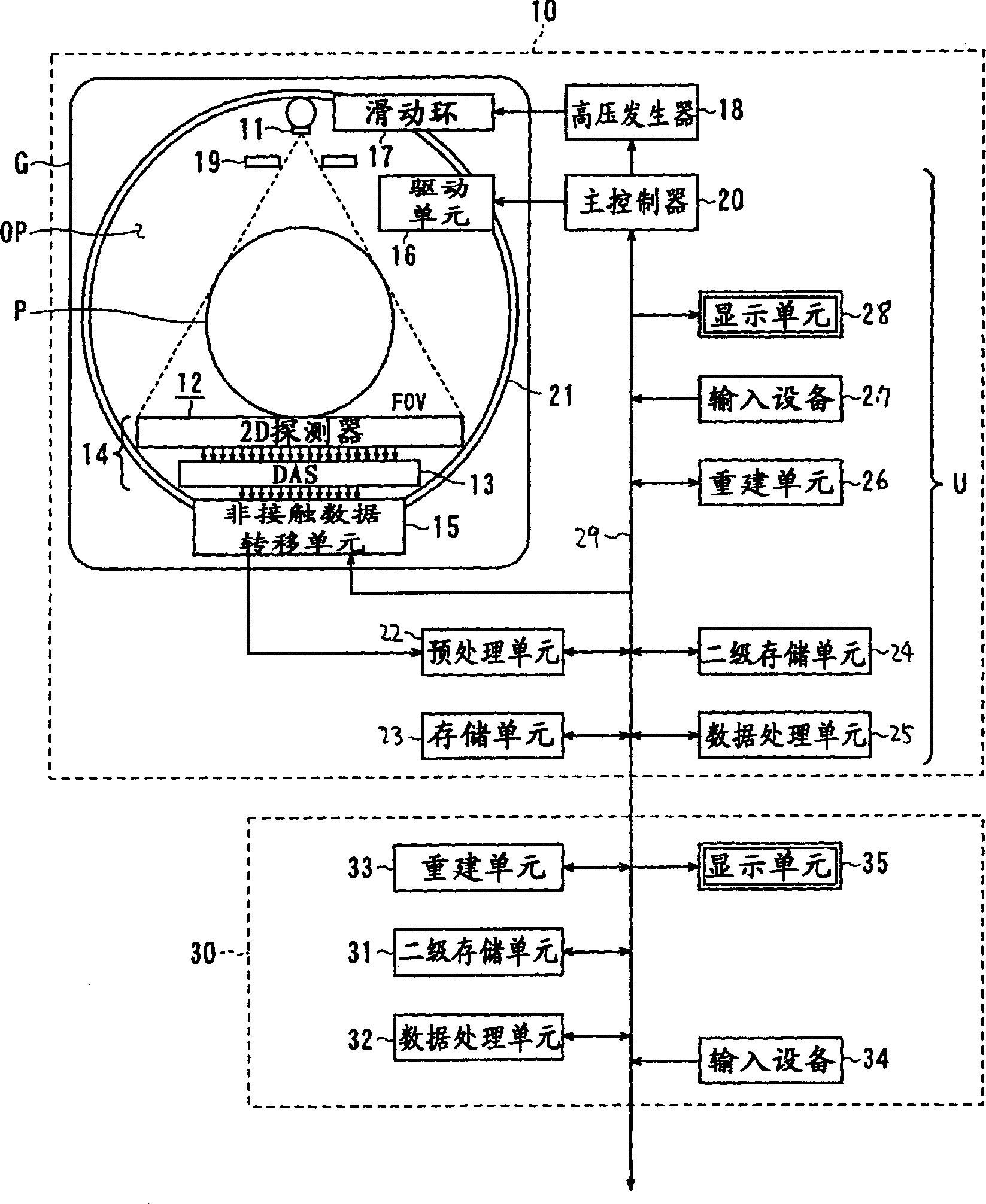
[0047] figure 1 A multi-slice X-ray CT scanner according to a first embodiment of the present invention is shown. This multi-slice CT scanner is capable of performing not only multi-slice helical scans, but also conventional scans (single-slice scans and multi-slice scans). like figure 1 As shown, the multi-slice CT scanner 10 includes a bed (not shown) on which a body (patient) to be examined is located, a base frame G having a diagnostic cavity OP for inserting a body P, for acquiring a body P The projection image data and a data processing unit U are used to control the work of the entire basic frame G, reconstruct the projection data into an image and display the final image.
[0048] The bed includes an upper deck that can be slid along its length by a bed drive unit (not shown). In most cases, the body P is positioned so that the axis of the body is parallel to the length of the bed.
[0049] ...
no. 2 example
[0081] Next, a second embodiment of the present invention will be described with reference to FIGS. 13-15.
[0082] The second embodiment relates to the technique of adjusting the voltage of each detector module 14n of the X-ray detection system 14 in the X-ray CT scanner. The X-ray CT scanner according to the second embodiment is substantially similar to the scanner according to the first embodiment described above. Parts similar to those in the first embodiment are denoted by similar reference numerals, and description will not be repeated here.
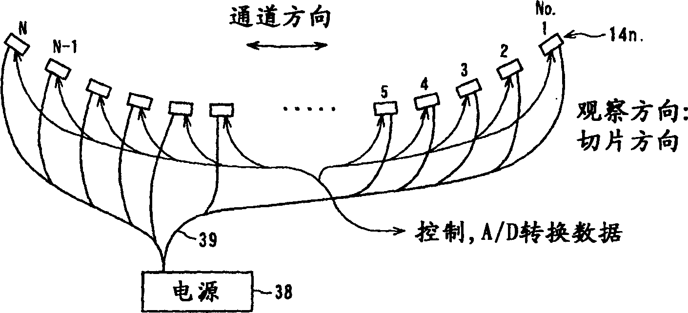
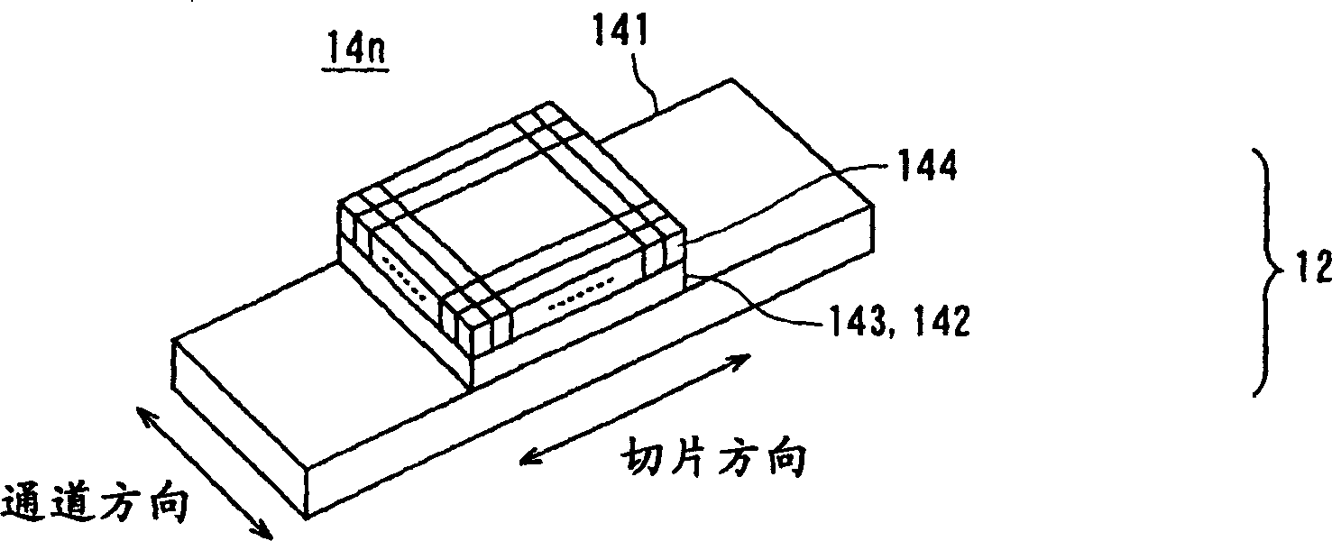
[0083] In the second embodiment, as shown in FIG. 13, each detector module 14n has a power connector 61 and a voltage regulator on the surface of the printed circuit board 141 facing the DAS. like Figure 14 As shown, the power connector 61 of each detector module 14n is connected to the output terminal of the power supply 63 through the cable 64, so that power is supplied to the voltage regulator 62 through the power connector 6...
no. 3 example
[0089] Refer below Figure 16 and 17 A third embodiment of the present invention will be described.
[0090] The third embodiment relates to the power supply line structure of each detector module 14n of the X-ray detection system 14 in the X-ray CT scanner. The X-ray CT scanner according to the second embodiment is basically similar to the scanner according to the first embodiment described above, except for the structure of the power cord.
[0091] In the X-ray detection system 14 according to the present embodiment, as Figure 16 As shown, the power lines supplying the (positive) power supply voltage to the individual detector modules 14n consist of flat metal strips 71 . More specifically, the power supply voltage is supplied from the power supply 72 to the X-ray detection system 14 through the cable 73 , and further supplied to each detector module 14 n in the X-ray detection system 14 through the metal strip 71 . like Figure 17 As shown, metal strip 71 has branches...
PUM
 Abstract
Description
Claims
Application Information