Clutch with intertial jointing

A clutch and inertia technology, applied in clutches, automatic clutches, mechanical equipment, etc., can solve problems such as large power transmission loss, easy heat generation, and incomplete separation

Inactive Publication Date: 2006-06-14
马燕翔
View PDF0 Cites 1 Cited by
  • Summary
  • Abstract
  • Description
  • Claims
  • Application Information

AI Technical Summary

Problems solved by technology

The former is mainly represented by the hydraulic coupling, although it can achieve no joint impact and prolong the life of the parts, but the separation is not complete, the power transmission loss is large, and it can hardly work at low speeds; the latter is mainly based on the positive displacement pump clutch. Although it can achieve stable joint and reduce energy consumption, it also has shortcomings such as incomplete separation, easy to generate heat, and short service life.

Method used


Image

  • Clutch with intertial jointing
  • Clutch with intertial jointing
  • Clutch with intertial jointing

Examples


Embodiment Construction

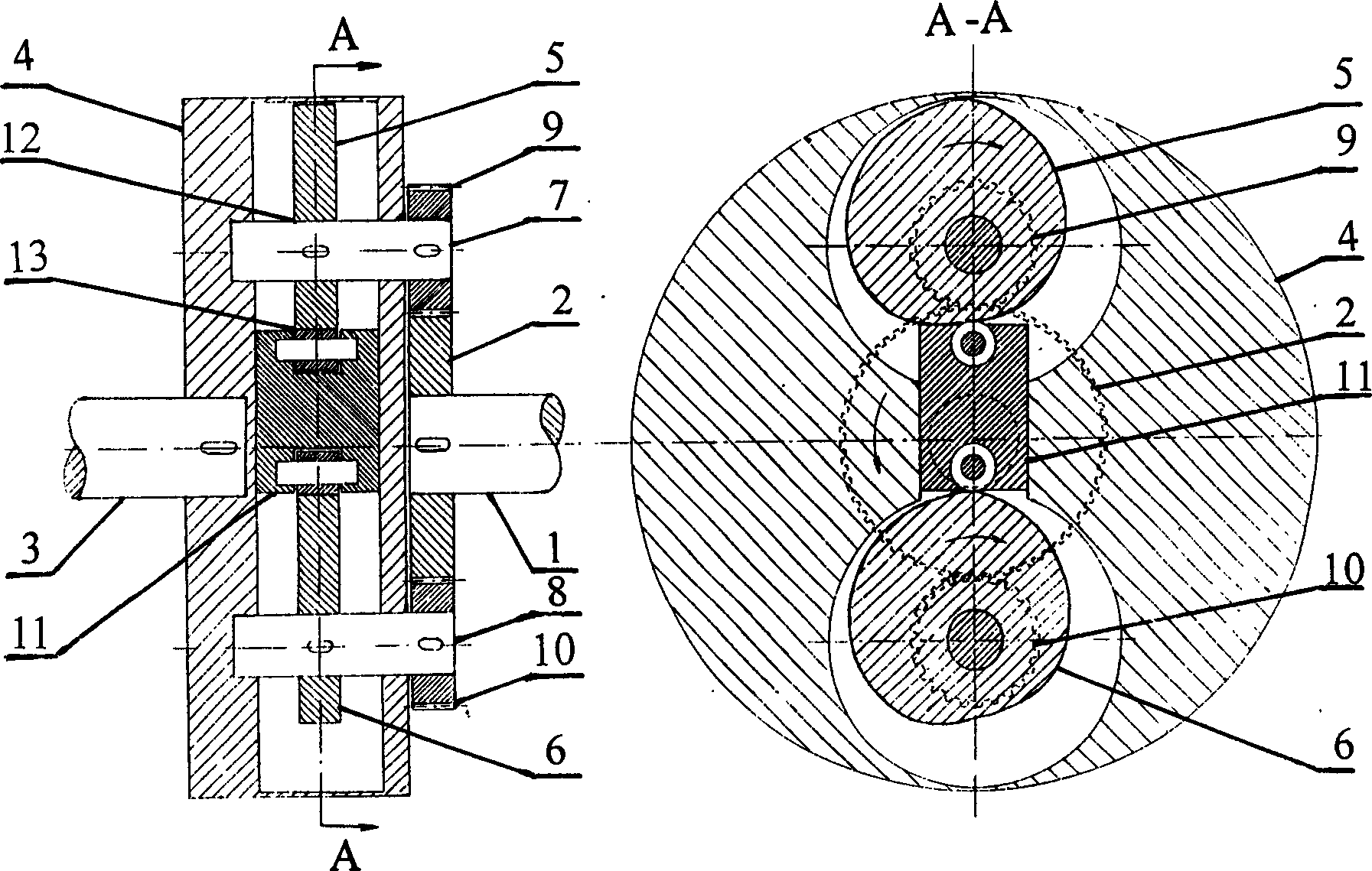
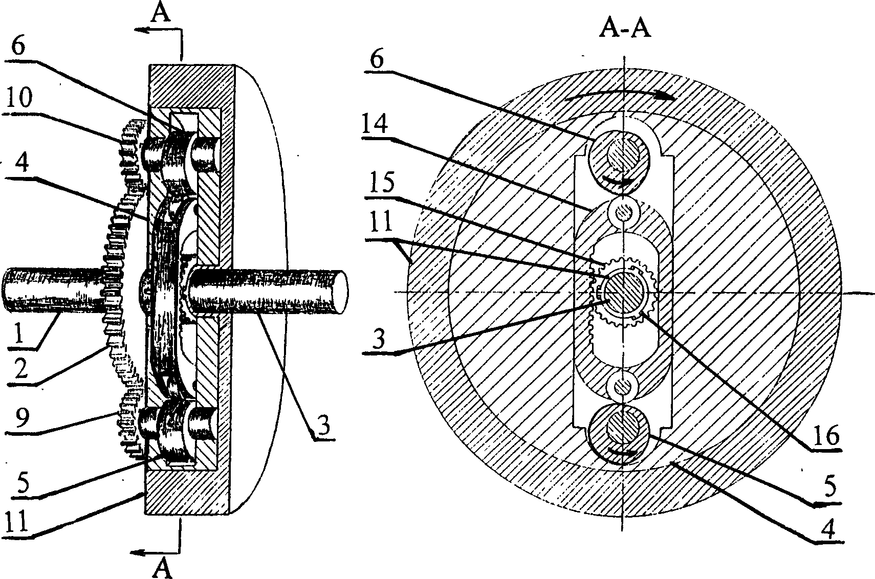
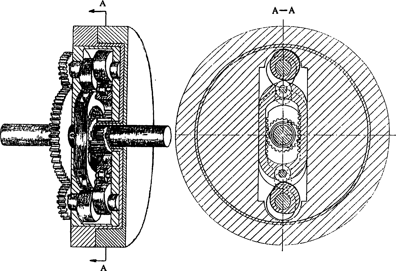
[0020] Such as figure 1 As shown, the clutch is mainly composed of: input shaft (1), input gear (2), output shaft (3), output turntable (4), cam (5), cam (6), camshaft (7), camshaft (8), transmission gear (9), transmission gear (10), and the pendulum (11) between two cams (5) cams (6), composition. Wherein transmission gear (9) and transmission gear (10) are two gears that are equal in size and the same number of teeth, and cam (5) and cam (6) are also identical, mainly here it is represented respectively for the ease of explanation of working principle.

[0021] When the input gear (2) rotates in the direction of the arrow in the drawing relative to the output turntable (4), the transmission gear (9) and the transmission gear (10) meshed with the input gear (2) drive the cam (5) and the cam (6) respectively. ) to rotate in the direction of the arrow in the drawing. Due to the effect of the profile curve of the cam (5), the stationary pendulum (11) is forced to move towards ...


PUM


Abstract

There is disclosed a positive clutch without clutch impact capable of long-time working in a semi-clutch state. It has a device capable of swinging reciprocately driven by a reciprocating motion mechanism made up of input shaft parts and output shaft parts. The moving reciprocately is produced by inlet shaft parts and outlet shaft parts. The reciprocating motion mechanism is blocked by pendulum inertia, so as to make the two shafts of the clutch be jointed together.

Description

1. Technical field: [0001] The present invention relates to a mechanical transmission, in particular to clutches. 2. Technical background: [0002] Various clutches can be divided into meshing type, friction type and hydraulic type according to the way of engaging elements. Although the meshing clutch has the advantages of small size, simple structure, fixed transmission ratio, etc., the disadvantage is that there is a certain impact and vibration when engaging, and it can only be engaged when the relative speed is very low or the rotation is almost stopped. Although the friction clutch can engage smoothly during operation, the friction plate will wear and generate heat during the engagement process, and cannot work in the half-clutch state. Due to the short engagement process time, there will still be a certain impact. Hydraulic clutches can be divided into flow hydraulic engagement clutches and hydrostatic pressure engagement clutches. The former is mainly represented by...

Claims


Application Information

Patent Timeline
Patent Type & Authority Applications(China)
IPC IPC(8): F16D43/04
Inventor 马燕翔
Owner 马燕翔
Why Eureka
Try Eureka