Optical fibre wave conducting type optical submodule

An optical sub-module and optical fiber waveguide technology, which is applied in the coupling of optical waveguide and optical fiber transmission, etc., can solve the problems of low coupling light alignment tolerance, long free space coupling distance, and low coupling efficiency, so as to achieve ample coupling Alignment tolerance, reduction of optical transmission dispersion, and improvement of optical output power

Inactive Publication Date: 2006-06-14
IND TECH RES INST
View PDF0 Cites 15 Cited by
  • Summary
  • Abstract
  • Description
  • Claims
  • Application Information

AI Technical Summary

Problems solved by technology

However, there is a crisis of low coupling light alignment tolerance in the three interfaces, and the light coupling problem of mode field mismatch is derived due to the different waveguide forms, so the overall light coupling efficiency will be difficult to improve
The sleeve-type optical sub-module mainly uses lenses to solve the problem of free-space optical coupling, and its optical coupling alignment tolerance is also compensated by lenses. The disadvantage is that the optical coupling efficiency is still not good, and the use of multiple le

Method used


Image

  • Optical fibre wave conducting type optical submodule
  • Optical fibre wave conducting type optical submodule
  • Optical fibre wave conducting type optical submodule

Examples


no. 1 example

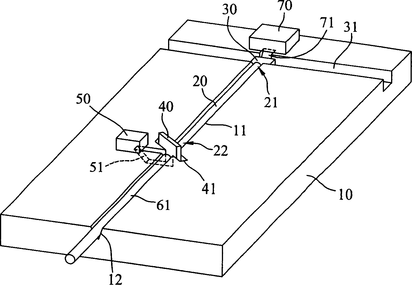
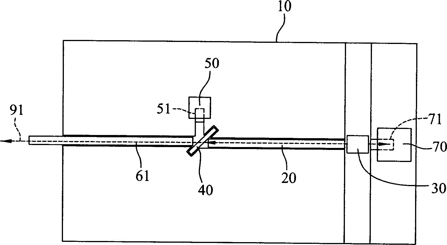
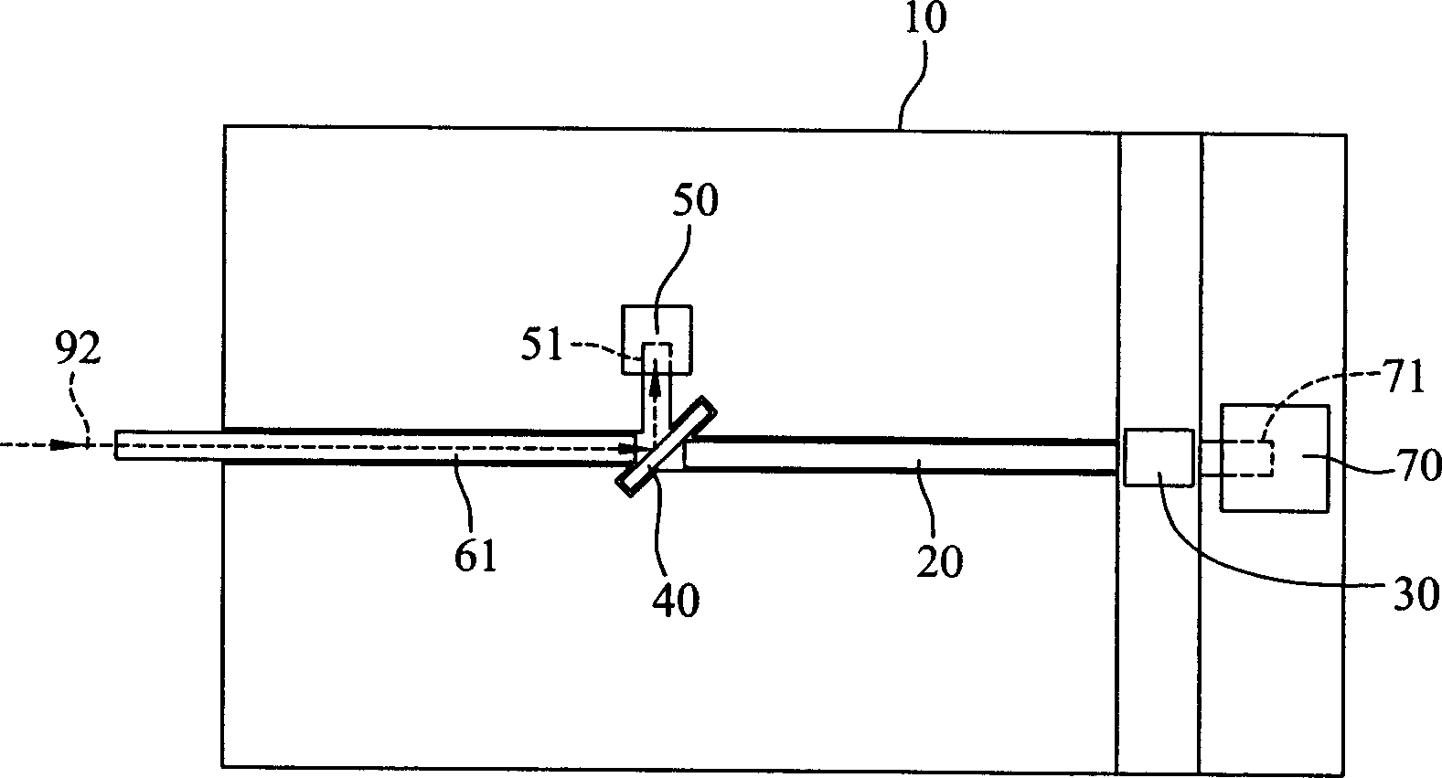
[0063] For the first embodiment of the dual-frequency optical sub-module disclosed in the present invention, please refer to figure 1 , including an optical table 10, a light emitter 30, a multimode fiber 20, a beam splitter 40, a light detector 50, and a single-mode fiber 61. The optical table 10 has two grooves 11, 12, a light emitter positioning groove 31, and a light splitter The positioning groove 41 is used to carry all optical components. The multimode optical fiber 20 has a front end 21 and an end 22 opposite to each other. The front end 21 of 20 is coupled to the light emitter 30, and the optical splitter 40 is installed in the positioning groove 41 of the optical splitter, and is joined with the rear end 22 of the multimode optical fiber 20, while the single mode optical fiber 61 is arranged in the groove 12, It is connected with the beam splitter 40 and communicated with the outside, and the photodetector 50 is arranged adjacent to the beam splitter 40 .

[0064] W...


PUM

PropertyMeasurementUnit
Lengthaaaaaaaaaa
Thicknessaaaaaaaaaa

Abstract

The invention relates to an optical fiber wave-guide optical secondary module that includes illuminator, multimode fiber, light splitter, optical fiber, and light checking device. The invention improves the permissible level of illuminator by multimode fiber that could save the extra contraposition mechanism and decrease cost and increase transmitting efficiency.

Description

technical field [0001] The invention relates to an optical sub-module, which is applied to an optical communication module in a passive optical network (PON) and a fiber-to-the-home (FTTH) network architecture, in particular to an optical fiber waveguide type optical sub-module. Background technique [0002] Bi-directional optical transceivers commonly used in passive optical network (PON) and fiber-to-the-home (FTTH) network architectures mainly have two forms: dual-frequency (Duplexer) and triple-frequency (Triplexer). Dual-frequency refers to the transmission of data (Data) and Voice (Voice) has two signal contents, while tri-band refers to the transmission of data, sound and video (Video) three signal contents. With the increasing demand for digital and analog image transmission, traditional two-way dual-frequency optical transceivers have been unable to meet the needs of the market. Demand, therefore, bi-directional tri-band optical transceivers will become the mainstre...

Claims


Application Information

Patent Timeline
IPC IPC(8): G02B6/42H04B10/25
Inventor 蔡明郎周明杰蔡伯晨吴宗远柯志祥张金生邱以泰朱俊勋陈荣泰
Owner IND TECH RES INST
Why Eureka
Try Eureka