
Integral external finned tube and method for manufacturing the same

A manufacturing method and integral technology, applied in tubular elements, lighting and heating equipment, heat exchange equipment, etc., can solve the problem of uncompact structure of heat exchange tube fins, limited effect of enhanced heat transfer, limited shape of finned tubes, etc. problem, to achieve enhanced steam condensation and convective heat transfer performance, compact structure, and simple manufacturing process

Inactive Publication Date: 2006-06-21
SOUTH CHINA UNIV OF TECH
View PDF2 Cites 25 Cited by
  • Summary
  • Abstract
  • Description
  • Claims
  • Application Information

AI Technical Summary

Problems solved by technology

[0004] The object of the present invention is to aim at the defects of the prior art, to provide an integral finned tube, the base tube and the fins are integrated, which not only has a compact fin structure, a large fin area, but also can clearly Increase the heat transfer rate and increase the heat transfer coefficient, solve the problems of large contact thermal resistance of zigzag finned tubes, easy fins to fall off, and limited heat transfer enhancement effect, and the fin structure of heat exchange tubes is not compact, and the shape of finned tubes is affected. The shortcomings of limited, easy to accumulate dust and difficult to clean

Method used


Image

  • Integral external finned tube and method for manufacturing the same
  • Integral external finned tube and method for manufacturing the same
  • Integral external finned tube and method for manufacturing the same

Examples


Embodiment Construction

[0027] The present invention will be further described below through embodiment and accompanying drawing, but the present invention is not limited to this embodiment.

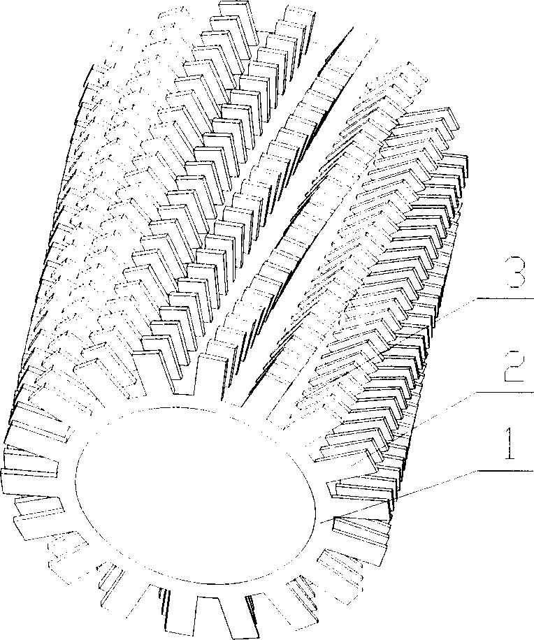
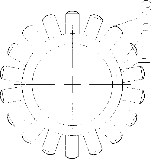
[0028] Such as figure 1 , 2 As shown, the integral finned tube of the present invention is composed of a base tube 1, fins 2, and channels 3. The channels 3 are distributed on the outer surface of the base tube 1 at a helix angle of 60 degrees, and between the channels 3 Fins 2 are distributed.

[0029] Such as figure 2 As shown, the cross-sectional shape of the base pipe 1 is circular, the channel 3 is trapezoidal, the periphery of the fins is fan-shaped, and the surface is flat.

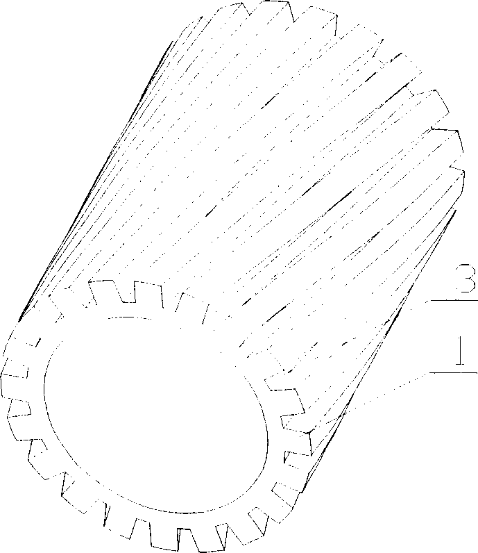
[0030] During processing, the base pipe 1 with the groove 3 is produced first by hot extrusion, cold extrusion, rolling or other die-casting methods, such as image 3 shown. A cutting tool 4 is then used to cut the base tube between the channels to form the fins, as Figure 4 shown.

[0031] Such as Figure 5 As shown, the ...


PUM


Abstract

This invention relates to one integral fin tube, which comprises base tube, fin slice, tank channel, wherein, the tanks are distributed on the base tube surface at 45 to 90 degree angle to the rotation angle; the tanks are distributed with parallel fin slices. The integral fin tube process method comprises the following steps: heat crushing, and cold grinding and processing tank channel by other casting method; then using tolls to cut down base tube between tanks to form fin slice; through heat crushing and cold crushing or other casting method to form fin by cutting the base tube between tanks.

Description

technical field [0001] The invention relates to an integral outer finned tube suitable for various types of heat exchange equipment and heating equipment in industries such as petroleum, chemical industry, refrigeration, metallurgy, and energy. [0002] The invention also relates to a method of manufacturing the integral outer finned tube. Background technique [0003] Outer finned tubes have been widely used in various types of heat exchange equipment and heating equipment. In order to improve its heat transfer performance, the common practice is to increase the heat transfer area of ​​the fin tube, strengthen the channel, and reduce the contact thermal resistance between the fin and the base tube. At present, the finned tubes commonly used in industry can be classified into two categories: one is finned tubes and base tubes processed separately, and then some means are used to combine the two finned tubes, such as cold-rolled embedded finne...

Claims


Application Information

Patent Timeline
Patent Type & Authority Applications(China)
IPC IPC(8): F28F1/36B21D53/06
Inventor 万珍平陆龙生汤勇
Owner SOUTH CHINA UNIV OF TECH
Learn More