
High speed gear spead increaser having automatic lubricating system

A high-speed gear, automatic lubrication technology, applied in the direction of belt/chain/gear, gear transmission, gear lubrication/cooling, etc., can solve the problem of reducing the service life of the speed-up gearbox, reducing cleanliness, high-speed gear speed-up structure and Use complication and other issues to achieve the effect of realizing circulation and simplifying the structure

Inactive Publication Date: 2006-06-28
GUIZHOU QUNJIAN PRECISION MACHINERY
View PDF0 Cites 3 Cited by
  • Summary
  • Abstract
  • Description
  • Claims
  • Application Information

AI Technical Summary

Problems solved by technology

[0002] In the existing high-speed gear speed increaser and its lubrication system, the oil pump is driven by a separate motor, which needs to be equipped with components such as check valves or electromagnetic devices. Before the high-speed gear speed up The structure and use of the gearbox are complicated
Due to the high speed of the high-speed gear speed increaser, the speed range is generally 3000-30000r / min, so that the temperature of the bearings, meshing gears and other parts in the speed increaser is very high, resulting in high temperature of lubricating oil and decline in cleanliness, reducing the speed increase Gearbox service life

Method used


Image

  • High speed gear spead increaser having automatic lubricating system

Examples


Embodiment Construction

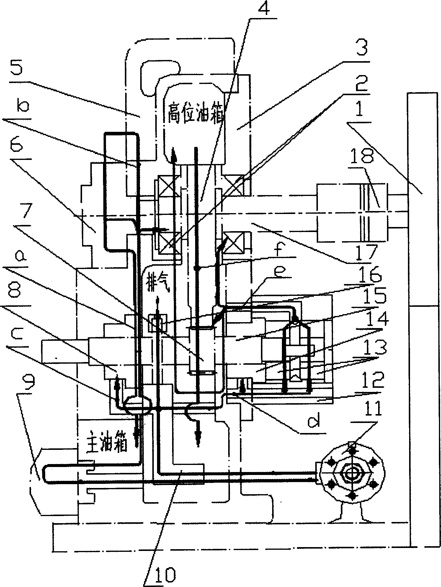
[0010] Embodiment of the present invention: select the oil pump 6 matched with the motor 1, and make each component. as per figure 1 Assemble as shown;

[0011] First, install the low-speed gear 4 and two ball bearings 2 on the low-speed shaft 16. The two ball bearings 2 are respectively installed on the left and right sides of the low-speed gear 4. The ball bearings 2 are supported on the box body 5, and then the oil pump 6 is installed. At the left end of the low-speed shaft 16; the high-speed gear 7 is installed on the high-speed shaft 15, the front radial bearing 8 is installed on the left side of the high-speed gear 7, and each bearing is supported on the box body 5, so that the low-speed gear 4 and the high-speed gear 7 meshing;

[0012] Secondly, the rear radial bearing 14 is installed on the case cover 3; two thrust bearings 13 are installed in the corresponding positions of the bearing housing (12); the bearing housing 12, the case cover 3 and the casing 5 are conne...


PUM


Abstract

The invention discloses a high speed gear speed increaser with auto-lubricating system, and its structure: an electric motor is connected with a low speed shaft, the low speed shaft engages with a high speed shaft by gear, an oil pump is installed on the low speed shaft, an oil circuit (a) is connected with a main oil tank, the oil pump, and a left-end ball bearing and an oil circuit (b); the oil circuit (b) is connected in turn with a filter, a cooler and an oil circuit block; the outlet of the oil circuit block is divided into three parts, one part is connected with an oil circuit (c) which is connected with a front radial bearing, one part is connected with an exhaust valve and another part is connected with an oil circuit (d); the oil circuit is connected in turn with a rear radial bearing, and two thrust bearings; one end of an oil circuit (e) is connected with the two thrust bearings and the other end is connected with a right-end ball bearing, the engaging place of the low speed gear and the high speed gear and a high level oil tank; an oil circuit (f) is connected with the high level oil tank and the main oil tank. The invention uses an electric machine to drive the speed increaser and the oil pump at the same time, having simple structure and good lubricating effect.

Description

Technical field: [0001] The invention relates to a mechanical transmission device, in particular to a gear speed increaser. Background technique: [0002] In the existing high-speed gear speed increaser and its lubrication system, the oil pump is driven by a separate motor, and it needs to be equipped with components such as a check valve or an electromagnetic device. Before the high-speed gear speed up The structure and use of the gearbox are complicated. Due to the high speed of the high-speed gear speed increaser, the speed range is generally 3000-30000r / min, so that the temperature of the bearings, meshing gears and other parts in the speed increaser is very high, resulting in high temperature of lubricating oil and decline in cleanliness, reducing the speed increase The service life of the gearbox. Invention content: [0003] The purpose of the present invention is to provide a high-speed gear speed increaser with an automatic lubrication system. The bearings and me...

Claims


Application Information

Patent Timeline
Patent Type & Authority Applications(China)
IPC IPC(8): F16H1/06F16H57/04
Inventor 陈远琴
Owner GUIZHOU QUNJIAN PRECISION MACHINERY
Learn More