Transmission device capable of producing combined motion output

A transmission device and compound motion technology, applied in the direction of transmission device, belt/chain/gear, mechanical equipment, etc., can solve the problem of high manufacturing precision and heat treatment process requirements of plane guide rails, affecting the movement accuracy of output parts, and easy heating of moving components, etc. problems, to achieve the effect of simple manufacturing process, simple structure, not easy to heat and wear

Inactive Publication Date: 2006-06-28
方亮 +1
View PDF0 Cites 4 Cited by
  • Summary
  • Abstract
  • Description
  • Claims
  • Application Information

AI Technical Summary

Problems solved by technology

The disadvantage of this transmission device is that other mechanisms are required to provide the force F, and the manufacturing precision and heat treatment process requirements of the elastically deformable planar guide rail are high, and the planar guide rail needs to bear pulsating positive pressure during the working process, especially during high-frequency motion. , the irregular vibration of the plane guide rail will affect the motion accuracy of the output piece. In addition, the device has a complex structure and high cost, and the moving components are prone to heat and wear quickly

Method used


Image

  • Transmission device capable of producing combined motion output
  • Transmission device capable of producing combined motion output
  • Transmission device capable of producing combined motion output

Examples


Embodiment

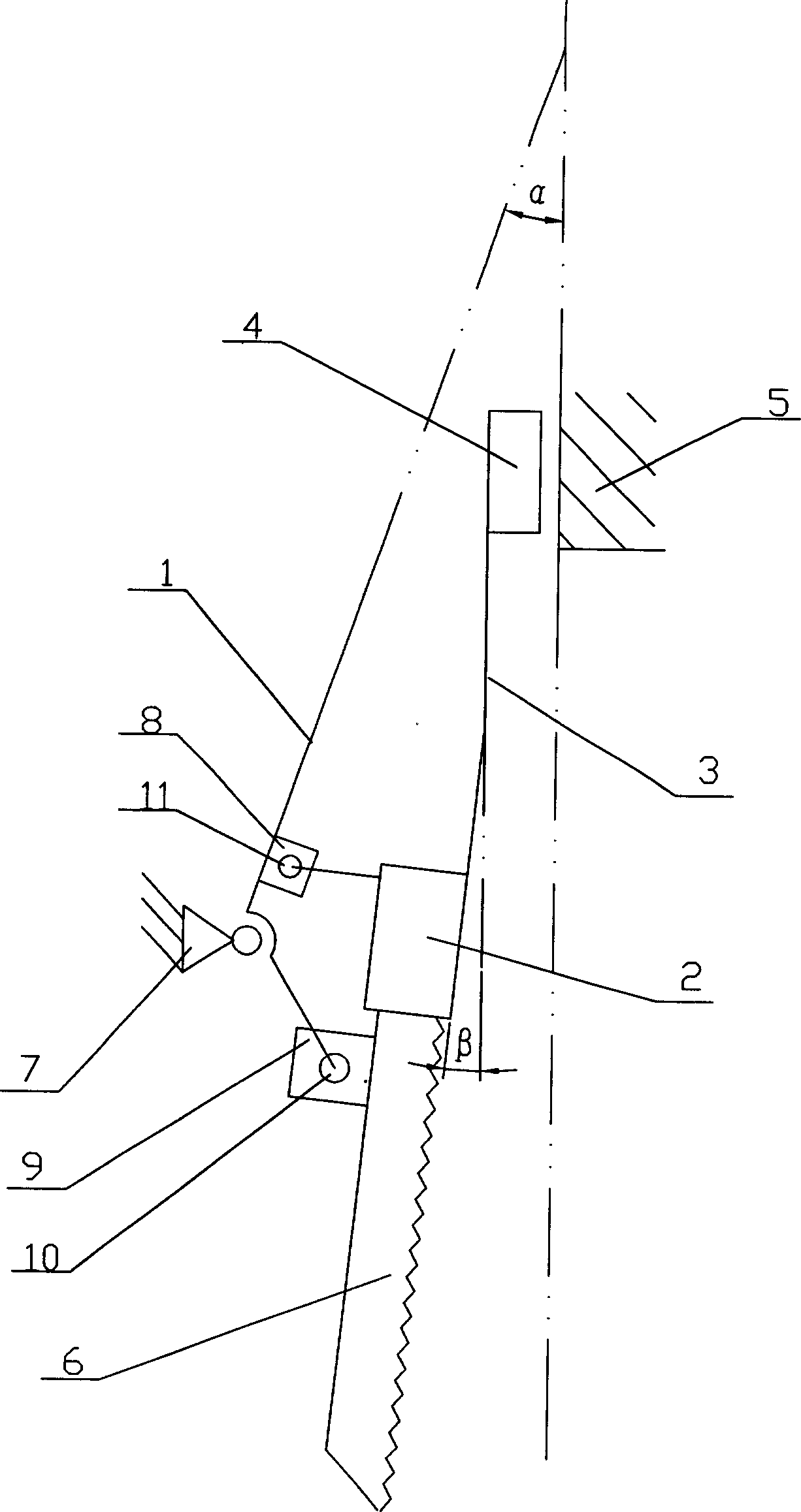
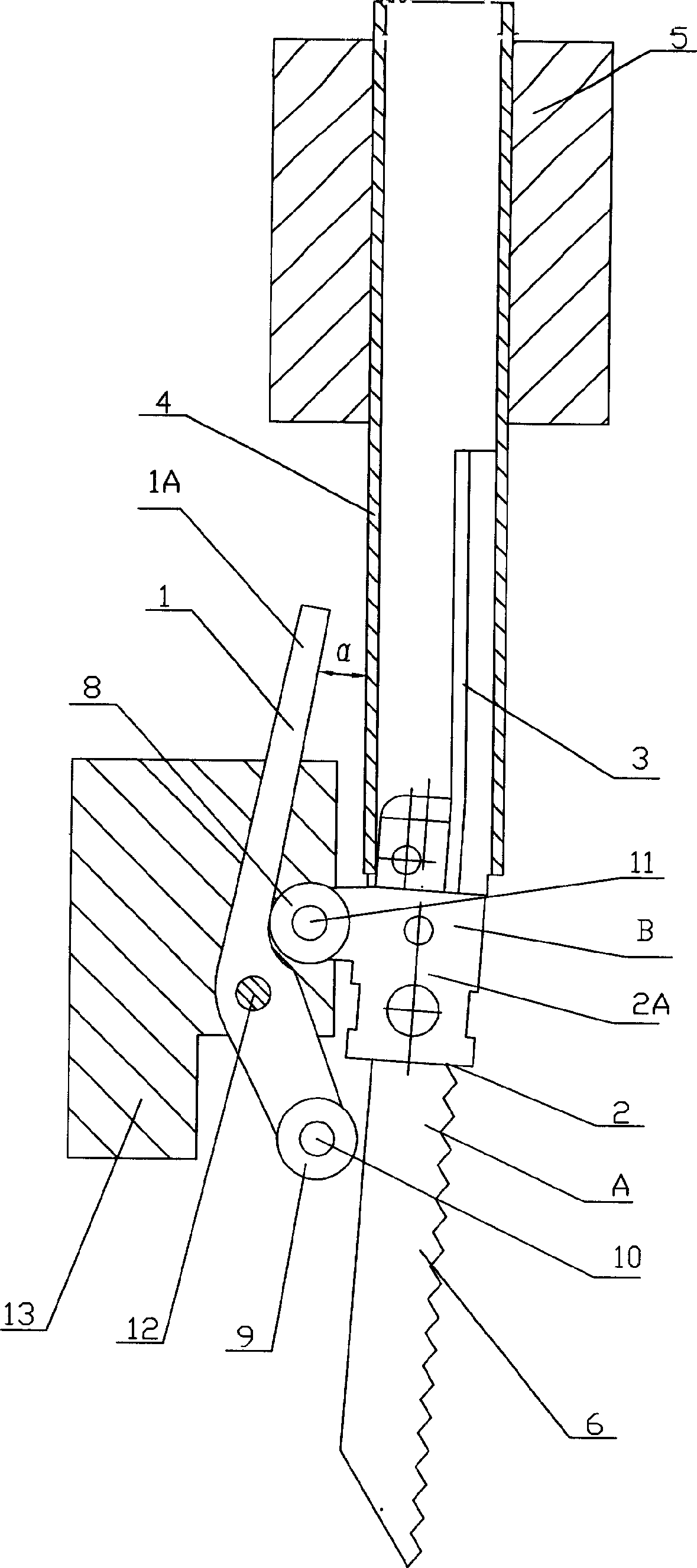
[0021] The principle diagram of the present invention is as figure 2 As shown, the schematic diagram of the structure is shown in image 3 As shown, it includes a swing rod 1, a composite moving part 2, an elastic part 3, and a sliding part 4, wherein the sliding part 4 is installed on the slideway provided by the guide part 5, and the compound moving part 2 is installed on the sliding part through the elastic part 3. On the part 4, the swing rod 1 is hinged on the frame 13 beside the compound moving part 2 through the hinge shaft 12, and one end of the swing rod (1) is in contact with the A end of the compound moving part 2, and the other end is provided with The inclined rod 1A forming an angle α with the moving direction of the sliding member 4 is in contact with the end B of the compound moving member 2 .

[0022] In order to reduce friction, the end B of the composite moving part 2 is in contact with the inclined rod 1A of the swing rod 1 through the roller 8 hinged the...


PUM


Abstract

The invention relates to a driving device for implementing compound motion output for an electric driven tool, comprising rocker, compound motion piece, element piece and sliding piece, where the sliding piece is installed on the runner of a guiding piece, the compound motion piece is installed on the sliding piece through the elastic piece, the rocker is hinged on a machine frame on one side of the compound motion through hinge shaft and one end of the rocker contacts with A end of the compound motion piece and the other end is provided with an inclined rod which forms an included angle alpha with the moving direction of the sliding and contacts with B end of the compound motion through the inclined rod. The invention needs no other mechanism to provide action force and its structure is simple and contact; and it is especially applied to the occasion of superposing rocking motion output to high frequency reciprocating linear motion.

Description

1. Technical field: [0001] The present invention is a transmission device for generating compound motion output for an electric tool, especially a transmission device that can generate swing motion output when performing reciprocating linear motion output. 2. Background technology: [0002] Among the existing transmission devices that can produce reciprocating linear motion output and swing motion output for electric tools, the principle of the transmission device that drives the movement of saw blades is as follows: figure 1 As shown, one end of the elastically deformable planar rail member 21 is fixed on the frame 24, and the other end leans against the return spring 28, and the return spring 28 can be compressed within the range of AB in the figure to produce elastic deformation, and the sliding member 22 moves along the The guide rail 21 is reciprocatingly output, and can swing around the hinge point 27 in the oblong hole 25 on the frame 24. The work piece 29 is fixed on...

Claims


Application Information

Patent Timeline
Patent Type & Authority Applications(China)
IPC IPC(8): F16H37/16
Inventor 方亮
Owner 方亮
Why Eureka
Try Eureka