
Power supply control device and method

A technology of power control and equipment, applied in the direction of electrical program control, data processing power supply, program control in sequence/logic controller, etc., can solve the problems of increased cost, increased PCB space, shortened battery life, etc., to reduce power supply noise effect

Inactive Publication Date: 2006-07-12
LEJIN ELECTRONICS KUNSHAN COMPUTER CO LTD
View PDF0 Cites 7 Cited by
  • Summary
  • Abstract
  • Description
  • Claims
  • Application Information

AI Technical Summary

Problems solved by technology

[0040] Therefore, changing the input capacitor of the central processing unit CORE power supply side, which is the main cause of noise, to POSCAP (a type of capacitor) is suitable, but unless all the capacitors and output capacitors of each power supply side are changed, the noise cannot be completely eliminated.
[0041] In order to completely eliminate noise, it is only necessary to change all ceramic capacitors, but because of the increase in PCB space and cost, it is a reality that it cannot be promoted.
[0042] Due to the above relationship, most notebook computers will not support the C4 state, and there is a shortcoming of shortened battery life due to this

Method used

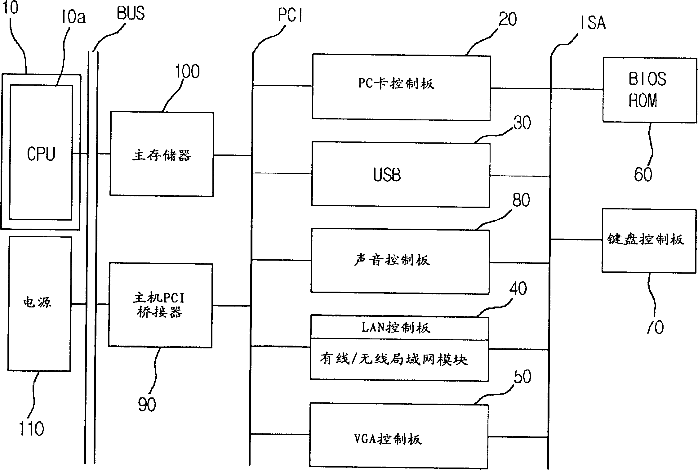

Image

  • Power supply control device and method
  • Power supply control device and method
  • Power supply control device and method

Examples


Embodiment Construction

[0083] Embodiments of the power control device and method of the present invention will be described in detail below with reference to the accompanying drawings.

[0084] Figure 4 In order to run the power management function of the present invention, the slave control unit 130 is intended to output an integrated map of voltages corresponding to the relevant modes (C1 / C2 / C3).

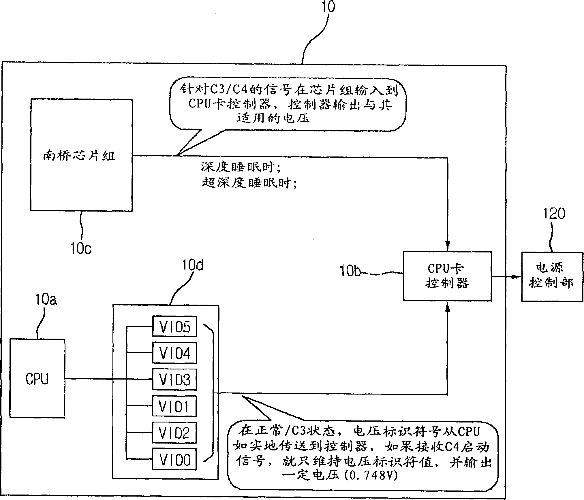
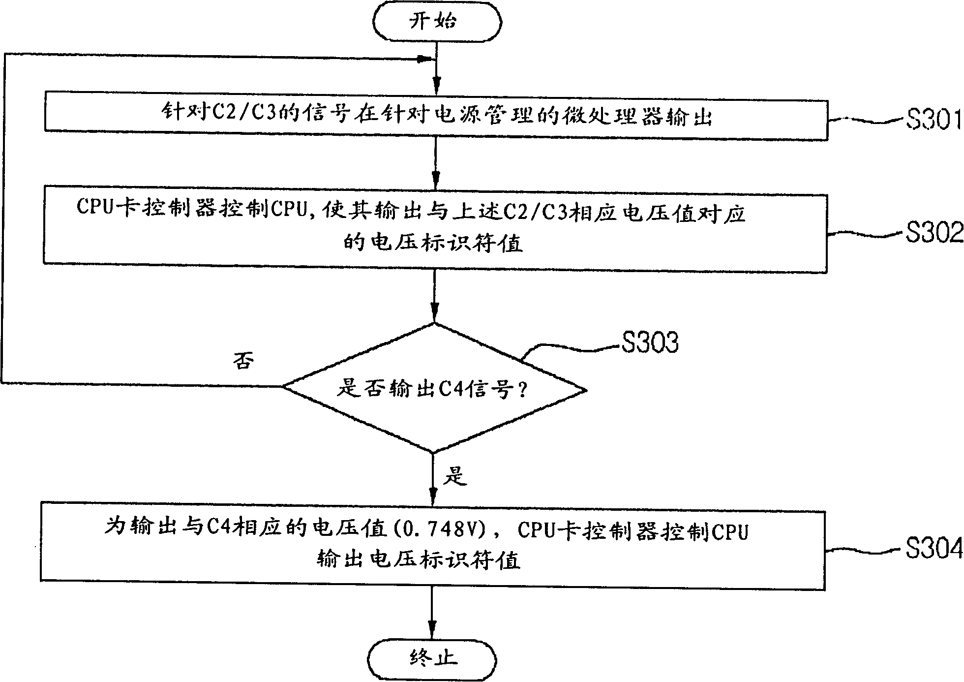
[0085] As shown in the figure, the system control unit 130 includes the following parts: according to the operating frequency of the main control unit 130a, output signals to a plurality of operation modes (C2 / C3 / C4) and the local area network or / and power supply as the operating system. The microprocessor of the control operation is controlled by the south bridge chipset 130c belonging to the signal output control part, which outputs the voltage identifier (VID0-VID 5) 130d corresponding to the voltage value of C2 / C3 in the above-mentioned operation mode, and Operate one or more CPU card control unit...


PUM


Abstract

The invention discloses a power control equipment and method, which comprises the following parts: signal output control part, voltage adjustment output part, voltage adjustment output control part, CPU card controller, voltage output part and alteration part, wherein the signal output control part outputs multiple motion mode signals according to the system motion frequency; the voltage adjustment output part adjusts or outputs at least one specific mode of multiple motion modes corresponding to the voltage value; the voltage adjustment output control part controls the voltage adjustment output part to output the corresponding voltage value to the motion mode; the CPU card controller controls and operates the power control part in connection with at least one output voltage; the voltage output part outputs the fixing voltage value; the alteration part transmits the fixing voltage value into system power of specific mode motion through output line. The invention can reduces the power noise in the portable device C4 condition greatly.

Description

(1) Technical field [0001] The present invention is to control the power supply of the connection system, especially in the action mode of the portable instrument system, when it is converted into an ultra-deep sleep mode (C4, Deeper Sleep Mode), in order to prevent the ripple voltage and current of the input power supply at a certain listening frequency A power control device and method capable of variably adjusting the voltage of a control unit in response to noise generated during internal variation. (2) Background technology [0002] In order to make effective use of the power used by the general system, if there is no signal input within a certain period of time, the system will be converted from the normal state (C2, Normal Mode) to the deep sleep mode (C3, Deepsleep); If there is no such thing or the operating frequency of the central processing unit operates within the range set in advance, it will switch to the ultra-deep sleep mode C4 to operate the system. [000...

Claims


Application Information

Patent Timeline
IPC IPC(8): G05B19/04G06F1/26
Inventor 苏廷桓
Owner LEJIN ELECTRONICS KUNSHAN COMPUTER CO LTD
Learn More