Single crank reciprocated flying shear

A single crank, flying shear technology, applied in the direction of shearing device, shearing machine equipment, shearing machine control device, etc., can solve the problems of high manufacturing cost, complex structure and movement, easy to break down, etc., and achieve easy manufacturing and maintenance , Simple structure, quick and easy adjustment

Inactive Publication Date: 2006-07-19
朱照铭 +1
View PDF0 Cites 5 Cited by
  • Summary
  • Abstract
  • Description
  • Claims
  • Application Information

AI Technical Summary

Problems solved by technology

[0005] The purpose of the present invention is to provide a new type of single-crank swing flying shears, which overcomes the disadvantages of the existing flying shears such as complex structure and movement, high manufacturing cost and easy failure

Method used


Image

  • Single crank reciprocated flying shear
  • Single crank reciprocated flying shear
  • Single crank reciprocated flying shear

Examples


Embodiment Construction

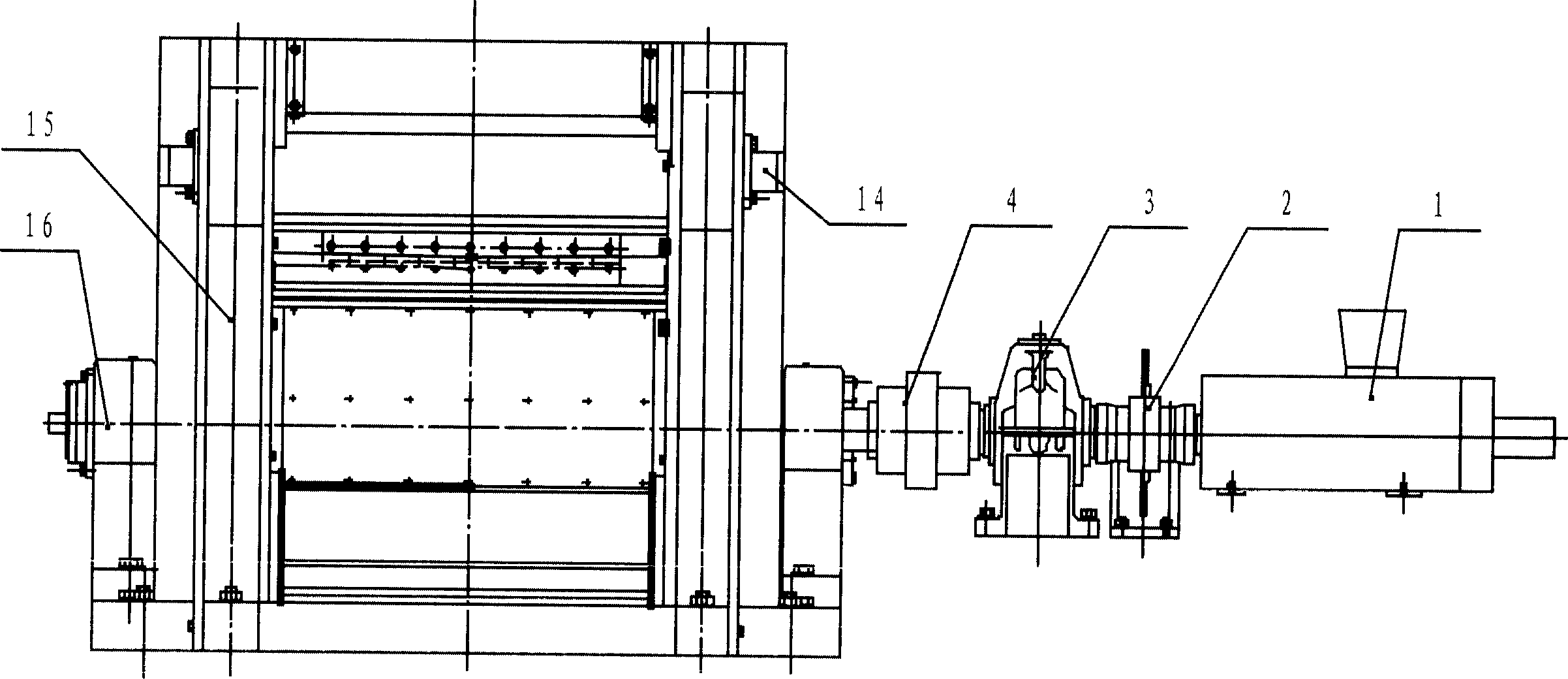
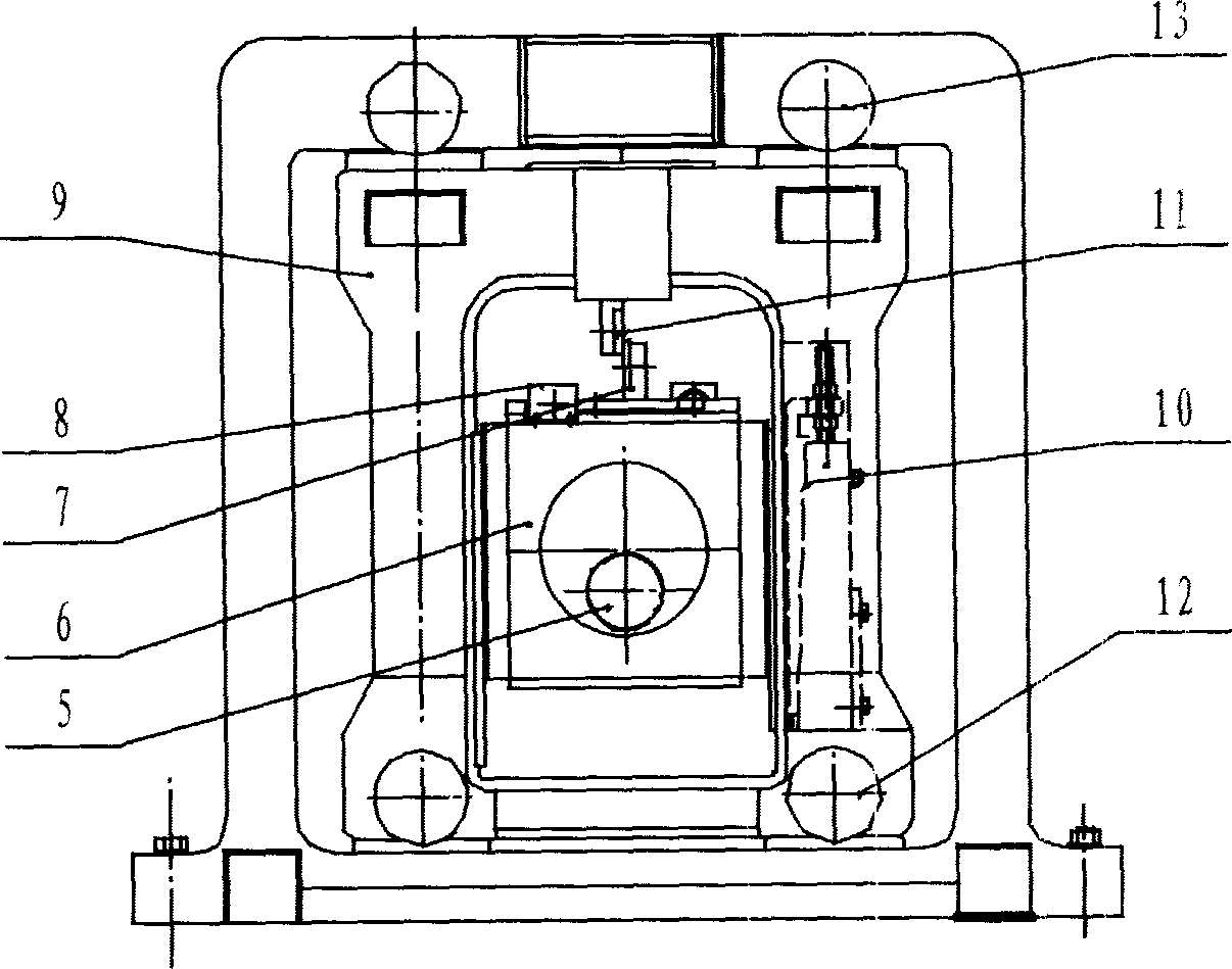
[0022] Depend on figure 1 , figure 2 It can be seen that the single crank swing flying shears of the present invention is composed of servo motor 1, braking device 2, gear box 3, safety coupling 4, crankshaft 5, box-shaped sleeve 6, lower knife and seat 7, cutting blade Clearance wedge adjustment device 8, mobile frame 9, triple wedge adjustment device 10, upper knife and seat 11, running roller 12, reaction roller 13, side guide roller 14, fixed frame 15, crankshaft bearing seat 16 , and other components.

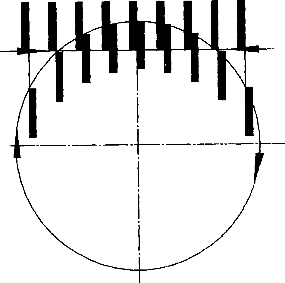
[0023] Depend on image 3 It can be seen that the single crank swing flying shear of the present invention is to drive the rotation of the single crank shaft by the transmission of the servo motor, thereby driving the relative motion of the relevant components (parts such as the box-shaped sleeve and the mobile frame) to form two completely different The running track of the upper and lower blades, that is, the running track of the lower blade is a circular motion, and...


PUM


Abstract

The invention discloses a single-crank swinging flying-shear in the continual synchronizing transverse-cut production line, which is characterized by the following: the servo motor drives the single-crank swinging flying-shear to rotate, which anchors the box-shaped liner to move vertically and horizontally; the linear speed of up-and-down blades keeps the same speed, which synchronizes the material-carrying speed with the shearing speed in the cutting region.

Description

technical field [0001] The invention discloses a novel single-crank oscillating flying shear, which is mainly used in a cross-cutting production line for continuous and synchronous cutting of ferrous and non-ferrous metal cold and hot strips in the metallurgical industry. Background technique [0002] Flying shear refers to the transverse shearing movement of the rolled piece, not only to meet the requirements of various sizing, but also to meet the requirements of shearing accuracy and productivity. [0003] Since the introduction of modern continuous rolling technology in my country's large iron and steel enterprises in the 1970s, flying shears have always been one of the important equipment imported, and the price is high. At the same time, with the development of other technologies such as electrical appliances, the imported flying shears are constantly being updated. However, the imported flying shear still has disadvantages such as complex stru...

Claims


Application Information

Patent Timeline
Patent Type & Authority Applications(China)
IPC IPC(8): B23D25/08B23D36/00
Inventor 朱照铭刘海昌
Owner 朱照铭
Why Eureka
Try Eureka