Mobile biomass liquefaction system

A biomass, mobile technology, used in the preparation of liquid hydrocarbon mixtures, oil industry, etc., to achieve compact structure, sufficient contact, and overcome the complex cooling system.

Inactive Publication Date: 2006-07-19
HUAZHONG UNIV OF SCI & TECH
View PDF0 Cites 13 Cited by
  • Summary
  • Abstract
  • Description
  • Claims
  • Application Information

AI Technical Summary

Problems solved by technology

The mobile liquefaction device requires as little energy consumption as possible (preferably self-sufficient), compact structure and suitable for various types of biomass raw materials, but the existing equipment cannot fully meet these requirements

Method used


Image

  • Mobile biomass liquefaction system
  • Mobile biomass liquefaction system
  • Mobile biomass liquefaction system

Examples


Embodiment Construction

[0026] The present invention will be described in further detail below in conjunction with the accompanying drawings.

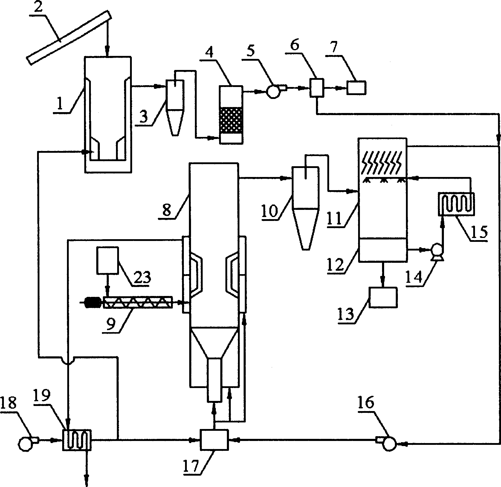
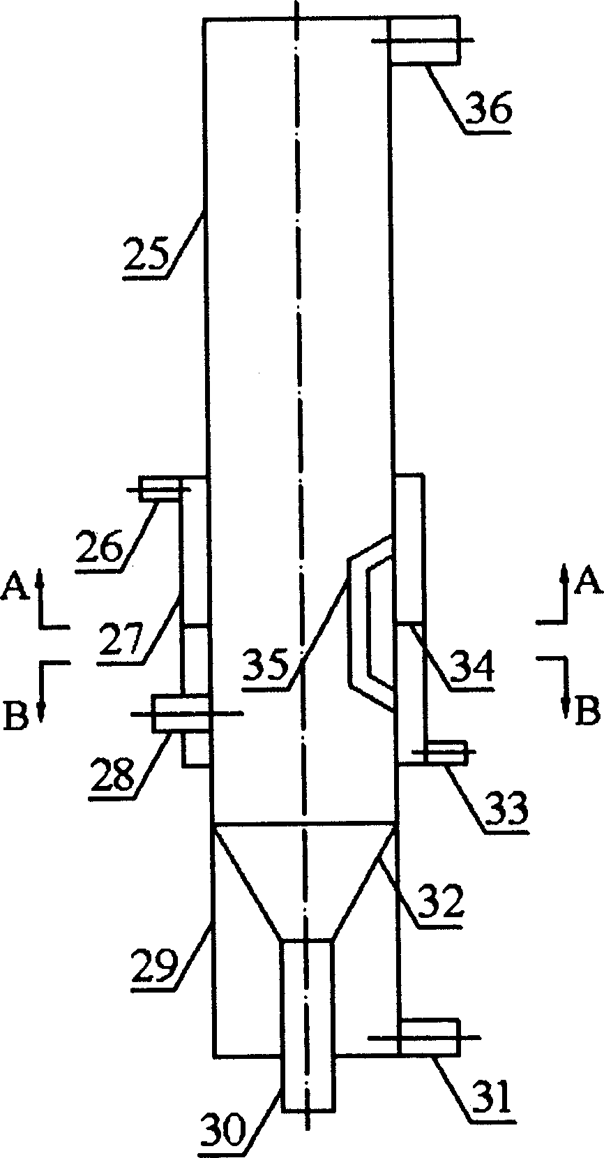
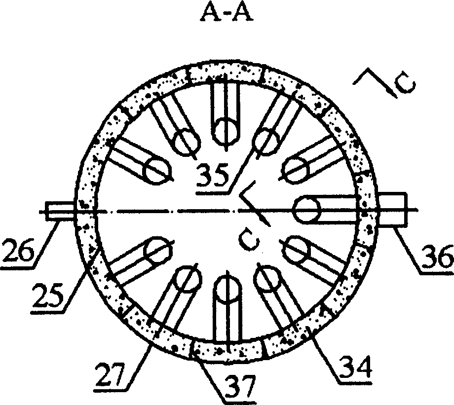
[0027] Depend on figure 1 As shown, the feeder 2, the biomass gasifier 1, the first cyclone separator 3, the tar cracking furnace 4, the fan 5, the gas storage tank 6 and the gas generator set 7 are connected in sequence, and the feed bin 23 and the screw feeder 9. Biomass pyrolysis furnace 8, second cyclone separator 10, cooling tower 11, liquid tank 12 and oil tank 13 are connected in sequence, liquid tank 12 is connected with heat exchanger 15 through circulation pump 14, heat exchanger 15 is connected with cooling The towers 11 are connected, the cooling tower 11 and the gas storage tank 6 are connected to the pre-combustion chamber 17 through the circulation fan 16, the air preheater 19 is connected to the pre-combustion chamber 17, the pre-combustion chamber 17 is connected to the biomass pyrolysis furnace 8, and the biomass pyrolysis furnace 8 is conne...


PUM


Abstract

The disclosed mobile biomass liquefaction system comprising: a biomass gasification furnace, a fuel decontamination plant, a fuel generating set, a biomass pyrolysis furnace with heat from the firing of gasified fuel and incondensable gas, a cooling tower, and a pretreatment device. This system realizes complete self-support for energy, can convert the biomass into bio-oil locally for further centralized treatment, and has high operation efficiency for wide application range.

Description

technical field [0001] The invention relates to a biomass liquefaction system. Background technique [0002] Biomass is a renewable resource that can be converted into liquid fuel. Its liquid products have the advantages of environmental friendliness, high energy density, easy storage, and easy transportation. They can be used as fuel for boilers, gas turbines, and engines, and can be extracted from them. valuable chemical products. [0003] A variety of different biomass pyrolysis liquefaction devices have been developed, such as the fluidized bed reactor developed by the University of Waterloo in Canada, the rotating cone reactor developed by the University of Twente in the Netherlands, and the vacuum reactor developed by Laval University in Canada. However, the lateral mixing characteristics of biomass and bed material in the fluidized bed reactor are not good, and the high ratio of carrier gas to material leads to serious wear of materials and equipment, low energy util...

Claims


Application Information

Patent Timeline
Patent Type & Authority Applications(China)
IPC IPC(8): C10G1/00
Inventor 陈汉平王贤华杨海平张世红杨国来邵敬爱徐明厚黄树红郑楚光
Owner HUAZHONG UNIV OF SCI & TECH
Why Eureka
Try Eureka