Controller driver and liquid crystal display apparatus using the same
A liquid crystal display device and driver technology, applied in the direction of instruments, static indicators, etc., can solve the problems of reducing power consumption, obstacles, etc., and achieve the effect of reducing power consumption
- Summary
- Abstract
- Description
- Claims
- Application Information
AI Technical Summary
Problems solved by technology
Method used
Image

Examples
no. 1 example
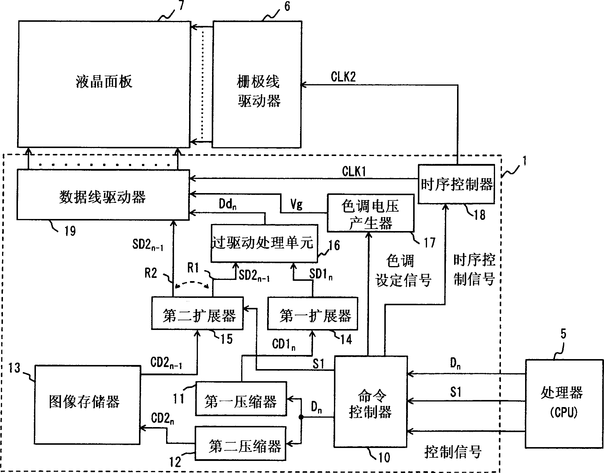
[0032] figure 1 The configuration of a liquid crystal display device having the controller driver 1 according to the first embodiment of the present invention is shown. The controller driver 1 has two compressors: a first compressor 11 and a second compressor 12, which perform compression independently of each other, thereby changing the Compression errors and compression errors contained in the compressed image data stored in the image memory 13 . Furthermore, in the controller driver 1, the command controller 10 receives the moving / still image switching signal S1 from the external processor 5, and the second expander 15 switches the output destination of the expanded image data according to the received signal S1 . The controller driver 1 is described in detail below. Elements having the same functions as in FIG. 16 are denoted by the same reference numerals and will not be described here.
[0033] Command controller 10 receives image data D from processor 5 n , a contr...
no. 2 example
[0064] Figure 8 The configuration of a liquid crystal display device having the controller driver 2 according to the second embodiment of the present invention is shown. The controller driver 2 differs from the controller driver 1 in the first implementation in that it has a D-type flip-flop (D-FF) 21 between the second compressor 12 and the image memory 23 and a D-FF between the image memory 23 and the D-FF22 between the second expander 15. Since the other components are the same as those in the controller driver 1, they are denoted by the same reference numerals and will not be described in detail here. The operation of the controller driver 2 having the D-FFs 21 and 22 is described below.
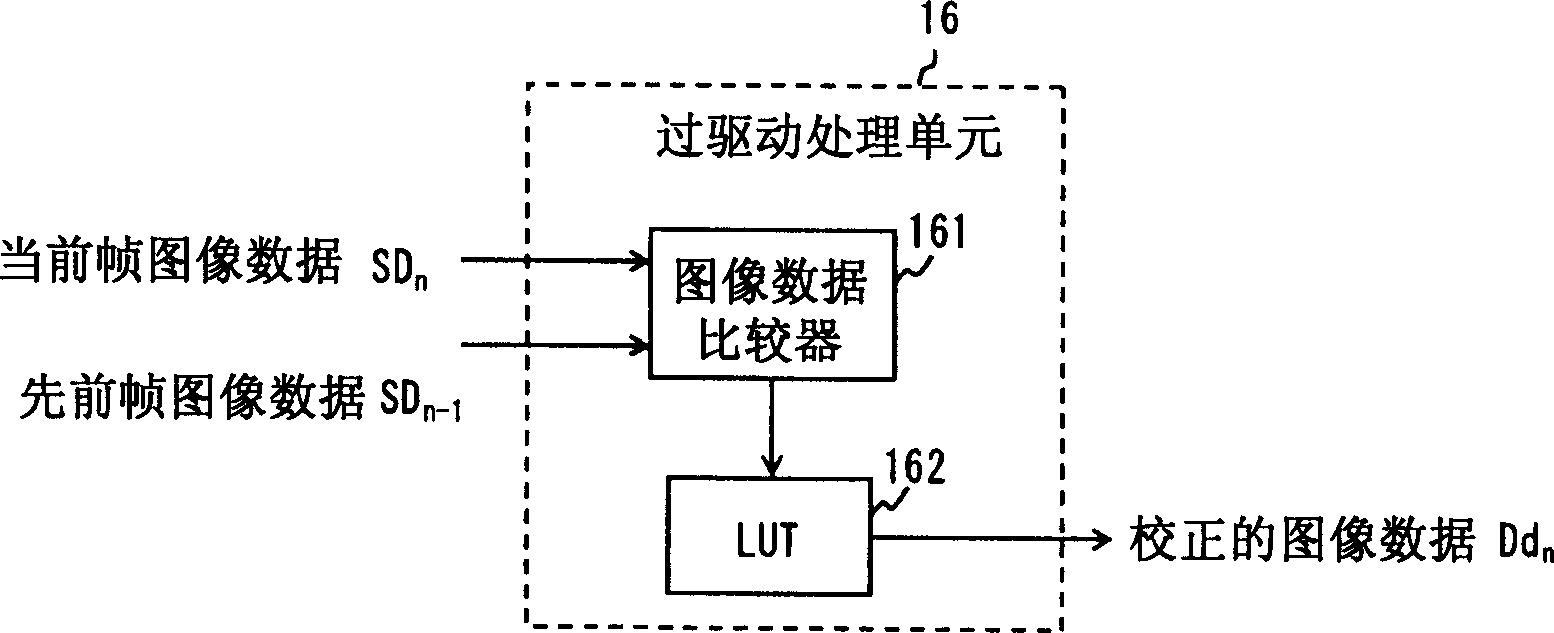
[0065] Figure 9A and 9B is a view showing the flow of image data from the first compressor 11 and the second compressor 12 to the overdrive processing unit 16 . Figure 9A and 9B The processing performed on image data of consecutive two pixels is shown. Figure 9A The input imag...
no. 3 example
[0073] Figure 11 is showing the configuration of a liquid crystal display device having the controller driver 3 according to the third embodiment of the present invention. The controller driver 3 is different from the controller driver 1 of the first embodiment in that one line of compressed image data is transferred in batches from the image memory 53 to the shift register included in the data line driver 59 591, and then input the compressed image data from the shift register 591 to the second expander 15 to perform expansion processing thereon. Expansion processing by the shift register 591 is described below.
[0074] First, one line of compressed image data is transferred in bulk from the image memory 53 to the shift register 591 in the data line driver 59 . Then, the compressed image data stored in the shift register 591 is transferred to the second expander 15 in which expansion processing is performed.
[0075] reference here Figures 12A-12C The data transmission...
PUM
 Abstract
Description
Claims
Application Information
 - R&D
- Intellectual Property
- Life Sciences
- Materials
- Tech Scout
- Unparalleled Data Quality
- Higher Quality Content
- 60% Fewer Hallucinations
Browse by: Latest US Patents, China's latest patents, Technical Efficacy Thesaurus, Application Domain, Technology Topic, Popular Technical Reports.
© 2025 PatSnap. All rights reserved.Legal|Privacy policy|Modern Slavery Act Transparency Statement|Sitemap|About US| Contact US: help@patsnap.com