

Fluid photoelectric dynamic detecting apparatus and application in viral infection test
A dynamic detection and fluid measurement technology, which is applied in measuring devices, material analysis through optical means, instruments, etc., can solve the problems of inability to control the concentration of poison in real time with high precision and the troublesome work of toxicology tests, and achieve easy operation, Avoid contamination, measure real-time and accurate results
- Summary
- Abstract
- Description
- Claims
- Application Information
AI Technical Summary
Problems solved by technology
Method used
Image

Examples
Embodiment 1
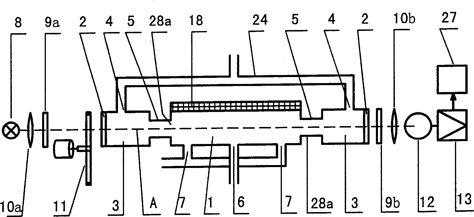
[0020] Embodiment 1: The specific implementation of the fluid dynamic detection device of the present invention
[0021] refer to figure 1 , fluid dynamic detection device of the present invention comprises two parts that two ends are provided with light transmission window 2 (light transmission window can be made by optical glass or other transparent material) and optical measurement system two parts; Optical measurement system mainly consists of light source 8 , optical chopper 11, lenses 10a and 10b, optical filters 9a and 9b, optical sensor 12 and signal amplifier 13 constitute; signal indicating instrument 27 can also be connected on signal amplifier 13 to facilitate the observation and monitoring of detection results; light source 8. The optical filter 9a, the lens 10a and the light chopper 11 are arranged on the outside of the light transmission window 2 on one side of the fluid measurement chamber 1; the optical filter 9b, the lens 10b, the optical sensor 12 and the si...
Embodiment 2
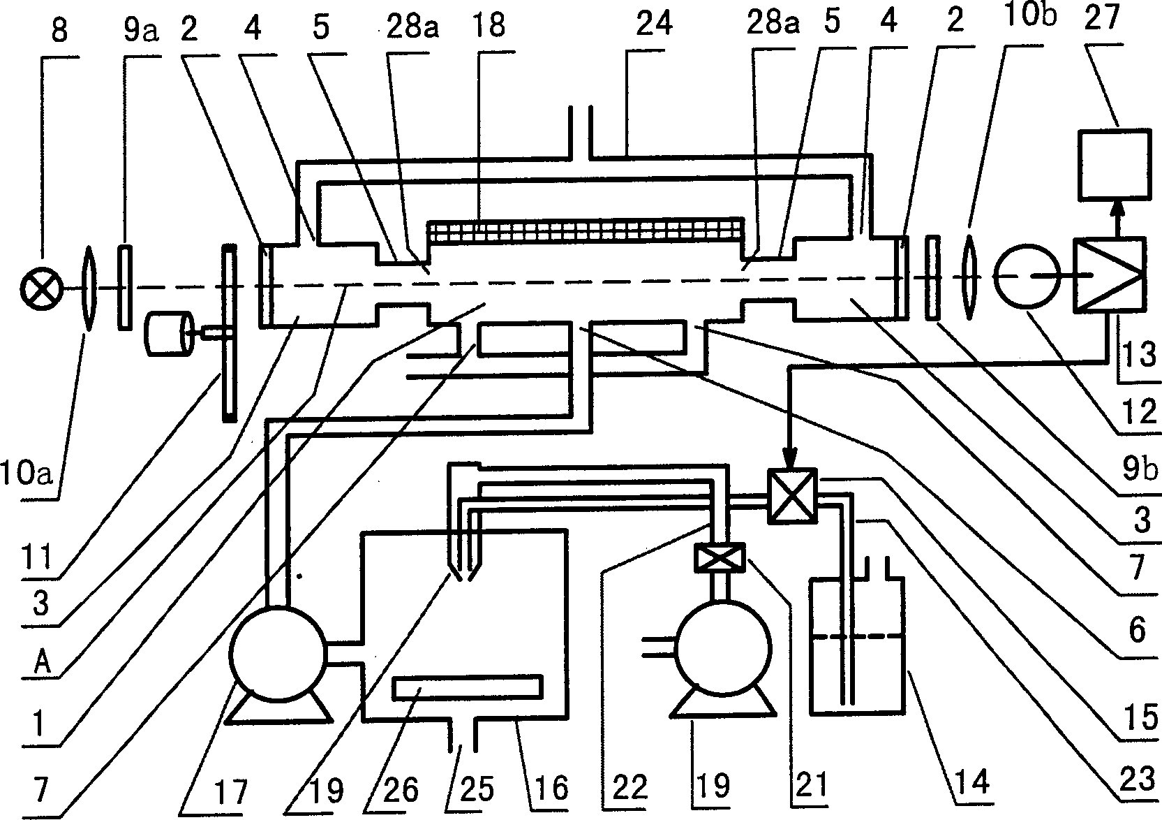
[0025] Embodiment 2: One of the specific implementations of the device of the present invention applied to animal poisoning experiments
[0026] When the device of the present invention is applied to the animal poisoning test, the structure of a dynamic poisoning test device that can control the dosage in real time and the general inhalation poisoning device is as follows: figure 2 shown.
[0027] refer to figure 2, the existing general inhalation poisoning device mainly consists of poisoning chamber 16, atomizing nozzle 20, air guide pipe 22, air regulating valve 21, air compressor 19, medicinal liquid container 14, catheter tube 23 and medicinal liquid regulating valve 15 etc. constitute, poisoning room 16 has an air outlet 25, can be provided with by the poisoned object placement support 26 in the poisoning room; The nozzle is connected to the air compressor 19, and the air guide tube is provided with an air regulating valve 21; one end of the guide tube 23 is connected...
Embodiment 3
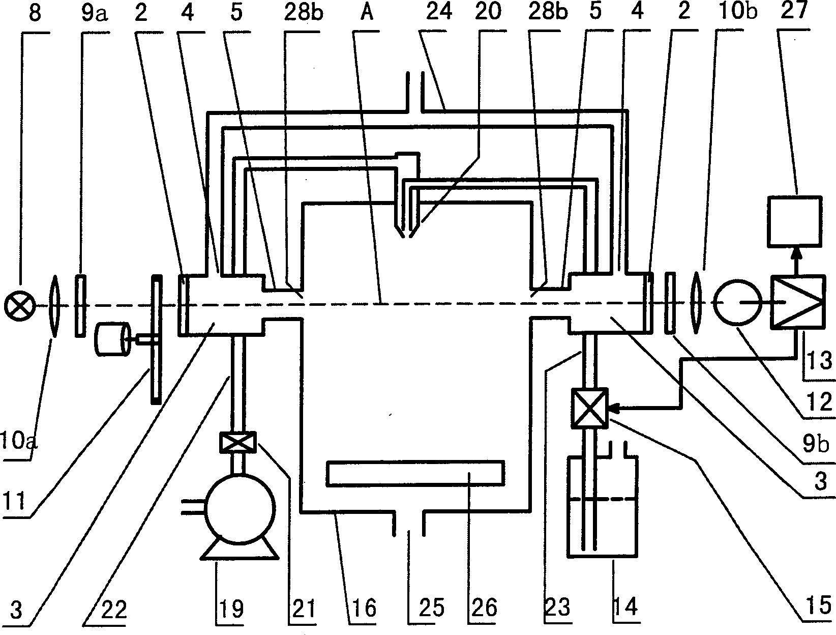
[0029] Embodiment 3: The second embodiment of the device of the present invention applied to animal poisoning test
[0030] When the device of the present invention is applied to the animal poisoning test, the structure of another dynamic poisoning test device that can control the dosage in real time with the general inhalation poisoning device is as follows: image 3 shown.
[0031] refer to image 3 with figure 2 ,Such as image 3 The present embodiment shown with the figure 2 The difference of the illustrated embodiment is that the device of this embodiment combines the fluid measurement chamber of the fluid dynamic detection device of the present invention and the poisoning chamber of the poisoning device into one. The device of the present embodiment directly uses the poisoning chamber 16 of the poisoning device as the fluid measurement chamber of the fluid dynamic detection device of the present invention; image 3 As shown, the fluid measurement chamber 1 of the ...
PUM
 Abstract
Description
Claims
Application Information