Method for controlling power-factor correct circuit

A power factor correction and control method technology, applied in the direction of output power conversion devices, electrical components, sustainable manufacturing/processing, etc., can solve the problems of complex debugging, many peripheral devices, poor performance indicators, etc., and reduce the size of the inductor , Reduce inductor ripple and heat, and improve the effect of adapting to the range

Active Publication Date: 2006-08-02
ZTE CORP
View PDF0 Cites 11 Cited by
  • Summary
  • Abstract
  • Description
  • Claims
  • Application Information

AI Technical Summary

Problems solved by technology

[0008] The purpose of the present invention is to provide a control method of a power factor correction circuit, which overcomes the shortcomings of many peripheral devices, complicated debugging and poor performance indicators in the prior art method, and improves the steady state and dynamic performance of the circuit while reducing the system cost. Eliminate the steady-state error of the system and improve the dynamic response performance; at the same time, the method of the present invention can reduce the current ripple voltage on the inductor, and double the frequency of the ripple current, thereby reducing the inductor ripple and heat generation, and improving the efficiency of the device

Method used


Image

  • Method for controlling power-factor correct circuit
  • Method for controlling power-factor correct circuit
  • Method for controlling power-factor correct circuit

Examples


Embodiment Construction

[0039] Below in conjunction with accompanying drawing, preferred implementation of the present invention is described in further detail:

[0040] The power factor correction device of the present invention includes the following parts:

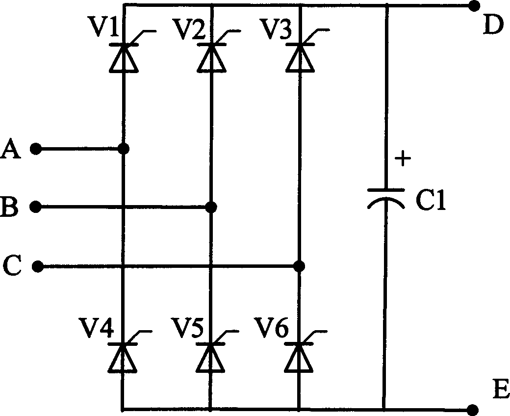
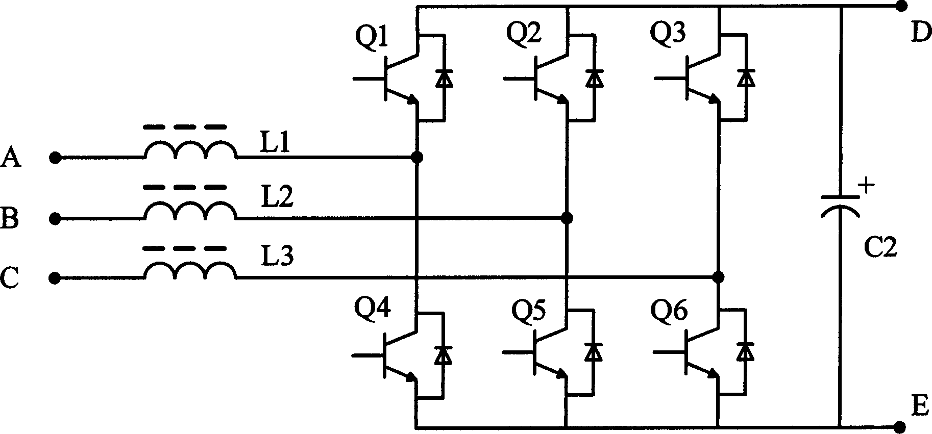
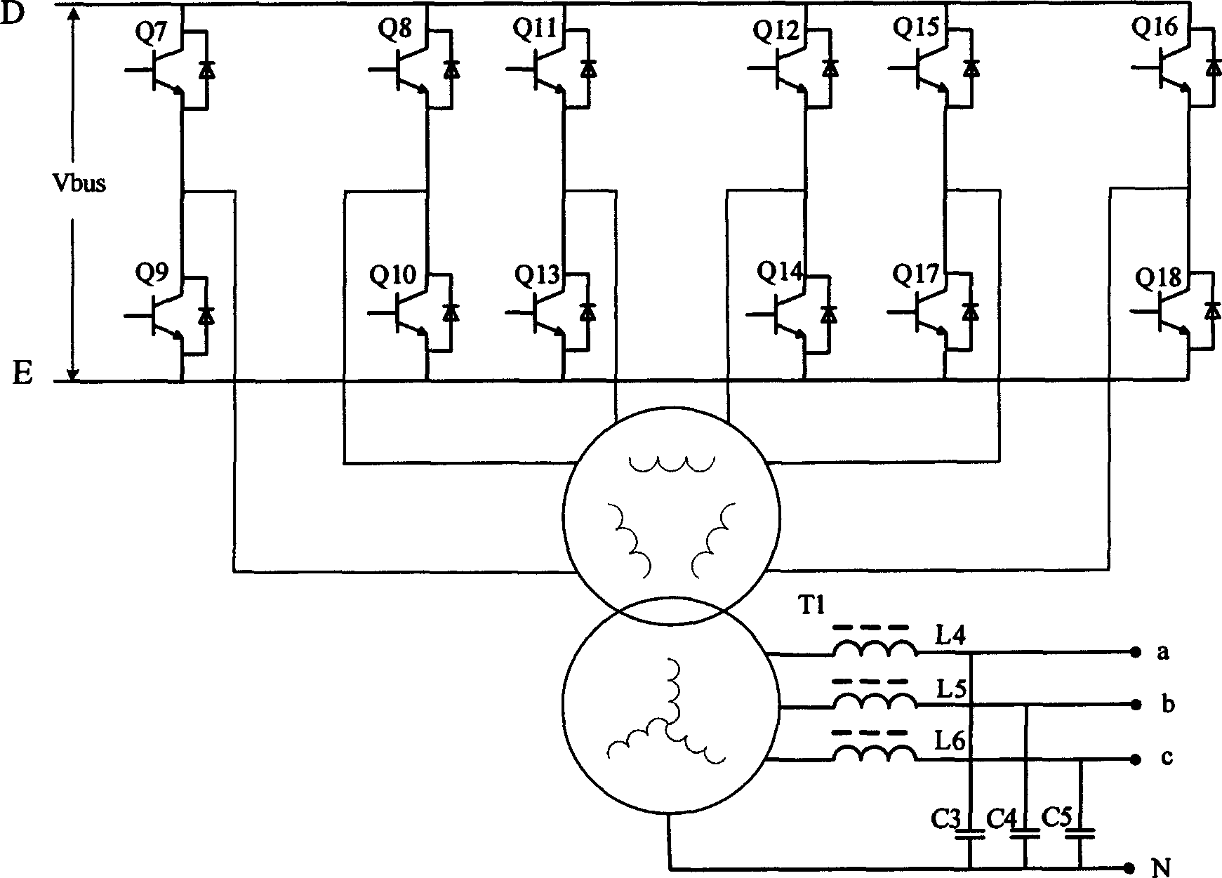
[0041] A rectifier bridge, used to receive the input voltage and convert the input AC voltage into a unipolar output voltage; a boost circuit composed of an inductor, two switch tubes, a diode three-phase rectifier bridge, and two capacitors; a controller, It is used to control the switching on and off of the switching tube, so as to achieve the purpose of making the inductor current equal to the predetermined waveform; a voltage detection circuit, which detects the AC input voltage or rectified voltage, which is the input voltage of the BOOST circuit; a current detection element or method, directly Detect or indirectly obtain the current flowing through the inductor.

[0042] The main functions of each part are: the rectifier bridge converts...


PUM


Abstract

This invention is controlling method of a kind of power factor correction circuit. The method concludes: the rectifier bridge transforms the inputting alternating current voltage to unipolar output voltage and provides to the said BOOST circuit. The said voltage detecting circuit and current detecting circuit provide kinds of needed input to the controller. Based on acquired input, the said controller calculates the switch tube on-and-off driving pulse of the said BOOST circuit. The switch tube of the said BOOST circuit accepts driving wave from the said controller. It makes the shape of inducted currents follow the shape of the input voltage provides by the rectifier bridge. Thus, the power factor correction is completed and the steady direct-current bus voltage output is provided. This invention decreases the system cost. It increases the stability and dynamic capability of circuit. It decreases the inductance ripple wave, radiation and inductance cubage. The efficiency is increased.

Description

technical field [0001] The invention relates to a control method of a power factor correction circuit in the field of power supply, in particular to the improvement of the digital control technology of the power factor correction circuit PFC in the field of uninterruptible power supply UPS. Background technique [0002] The existing medium and high-power three-phase power factor technology usually adopts the method of thyristor phase-controlled rectification, or the method of uncontrolled rectifier bridge plus boost BOOST circuit. Since the conversion power of the three-phase UPS is large and consumes a lot of electric energy, the input power factor of the equipment is required to meet the standard; in addition, the three-phase UPS has many types of loads, including resistive, inductive, capacitive and rectified nonlinear loads and combinations of several loads. It is required that the UPS can adapt to various loads, has a strong overload capability, and the output has an is...

Claims


Application Information

Patent Timeline
Patent Type & Authority Applications(China)
IPC IPC(8): H02M1/14
CPCY02P80/10
Inventor 李艳玲林东华
Owner ZTE CORP
Why Eureka
Try Eureka